
A multi-axis synchronous motion control method for a flexible electronic gearbox

A multi-axis synchronization and motion control technology, applied in gear tooth manufacturing devices, components with teeth, belts/chains/gears, etc., can solve problems such as high price and restricting the development of gear processing equipment manufacturing industry.

Active Publication Date: 2020-09-29
HEFEI UNIV OF TECH
View PDF6 Cites 0 Cited by
  • Summary
  • Abstract
  • Description
  • Claims
  • Application Information

AI Technical Summary

Problems solved by technology

These foreign gear CNC systems are not only expensive, but also have a relatively strict market access system, which seriously restricts the development of my country's gear processing equipment manufacturing industry.

Method used


Image

  • A multi-axis synchronous motion control method for a flexible electronic gearbox
  • A multi-axis synchronous motion control method for a flexible electronic gearbox
  • A multi-axis synchronous motion control method for a flexible electronic gearbox

Examples


Embodiment 1

[0051] The tool parameters are: right-hand hob, normal modulus m n Is 1, the number of hob heads Z b Is 1, the hob pressure angle α is 20°, the hob helix angle λ is 1.93°, the installation angle γ is 23.07°, and the hob axial feed is V Z Y > 0; The parameters of the workpiece to be processed are: gear normal modulus m n Is 1, gear teeth number Z c It is 49, the gear pressure angle α is 20°, the gear is right-handed, the helix angle β is 25°, and the total position control time is 11ms, which is divided into 11 position control time points.

[0052] The specific operation steps of the flexible electronic gearbox multi-axis synchronous motion control method are as follows:

[0053] (1) Determine the type of gear processing by the "diagonal rolling method"

[0054] When using the "diagonal hobbing method" to process helical cylindrical gears, because the tool moves along the Z axis, the C axis produces additional rotation to meet the geometric relationship of the spiral line; when there ...

Embodiment 2

[0094] The tool parameters are: left-hand hob, normal modulus m n Is 2, the number of hob heads Z b Is 1, hob pressure angle α is 20°, hob helix angle λ is 2.01°, installation angle γ is 22.99°, hob axial feed V Z > 0, hob tangential feed V Y n Is 2, gear teeth number Z c It is 27, the gear pressure angle α is 20°, the gear is left-handed, the helix angle β is -25°, and the total position control time is 11ms, which is divided into 11 position control time points.

[0095] The specific operation steps of the multi-axis synchronous motion control method of the flexible electronic gearbox are as follows

[0096] (1) Determine the type of gear processing by the "diagonal rolling method"

[0097] When using the "diagonal hobbing method" to process helical cylindrical gears, because the tool moves along the Z axis, the C axis produces additional rotation to meet the geometric relationship of the spiral line; when there is a tool shifting process requirement, the tool moves along the Y axis...


PUM


Abstract

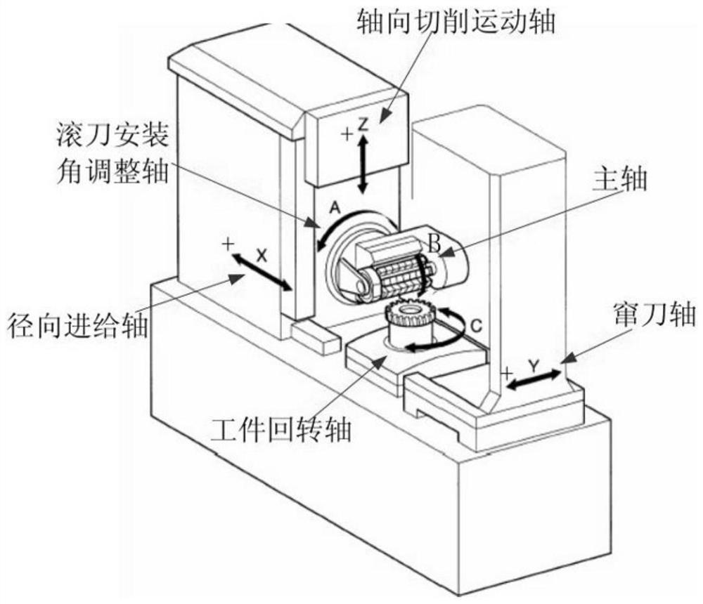
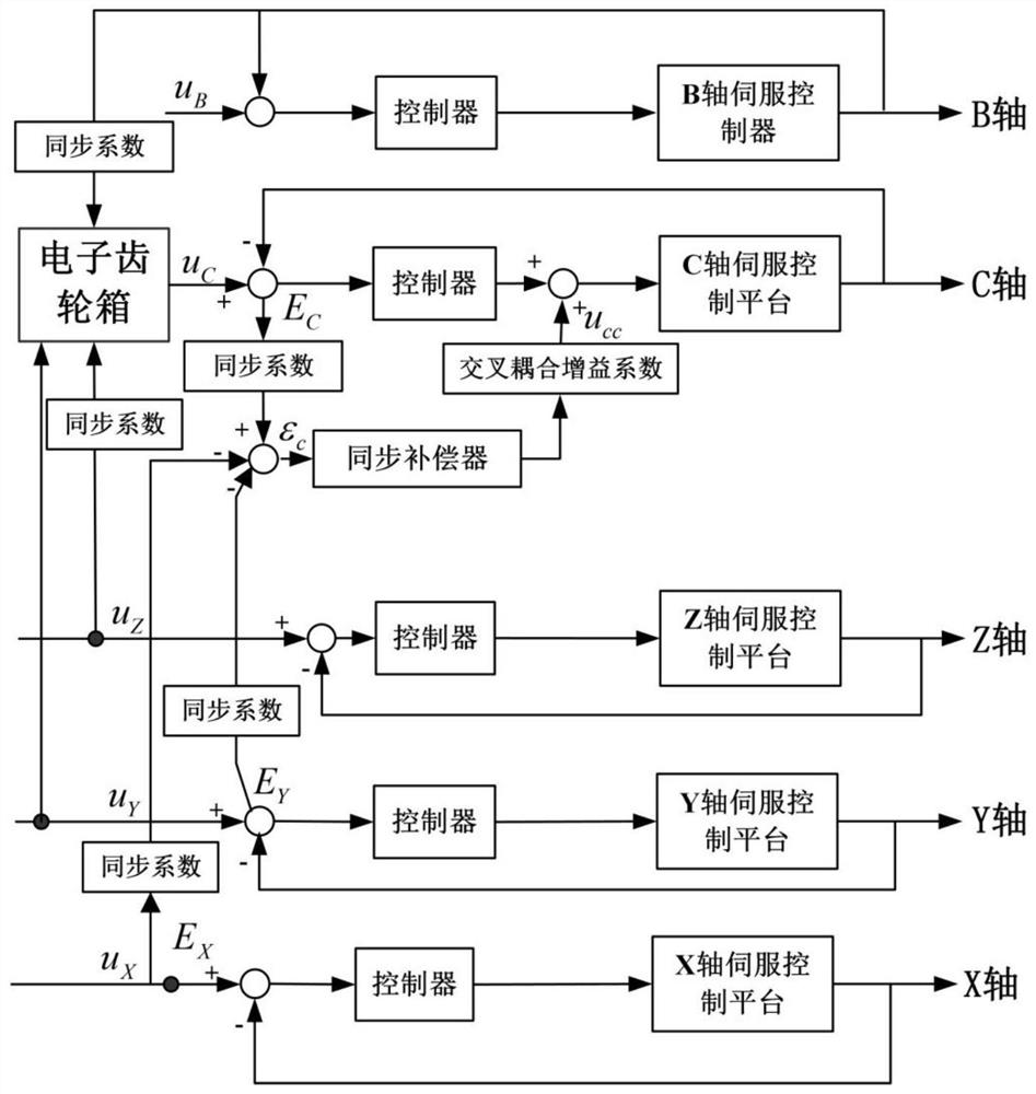
The invention relates to a multi-axis synchronous motion control method of a flexible electronic gear box and belongs to the technical field of numerically-controlled machine tools. The method is suitable for a numerically-controlled gear hobbing machine. According to a processing principle of the numerically-controlled gear hobbing machine, a function relation between gear geometric errors and track errors of all motion shafts of a machine tool is established; according to track error parameters of all the motion shafts, a processing error mathematical model of the tooth profile, tooth pitchand lead variation at each position control time point is established; a decoupling compensation model is established and used for calculating the compensation amount required by a workpiece rotationshaft at the next position control time point; processing error numerical values at all the position control time points are calculated, processing error average absolute values and processing error total compensation amounts obtained by not adopting the synchronous control method and obtained by adopting the synchronous control method in position control total time are obtained, and multi-axis synchronous motion control is achieved. By means of the multi-axis synchronous motion control method, the processing speed can be increased by 20-30%, the debugging time of the machine tool is shortenedby 10-30%, and accordingly the production cost is lowered.

Description

Technical field [0001] The invention belongs to the technical field of numerical control machine tools, and in particular relates to a method for controlling a multi-axis synchronous operation of a numerical control gear hobbing machine with a coupling relationship. Background technique [0002] For general CNC gear processing machine tools to realize multi-axis motion control, two DC motors are generally driven by a set of DC speed regulating device, the armatures of the two motors are connected in series, and the excitation coils are connected in parallel. In order to maintain speed synchronization, the two motor shafts must be rigidly connected. Only one of the two motors provides speed feedback data; at the same time, two sets of AC frequency conversion speed regulation systems respectively control the two AC frequency conversion or servo motors as the master and slave shafts. The two motors each provide their own speed feedback data. In order to maintain speed synchronizati...

Claims


Application Information

Patent Timeline
Patent Type & Authority Patents(China)
IPC IPC(8): B23F23/00
CPCB23F23/006
Inventor 田晓青李旦吴雨
Owner HEFEI UNIV OF TECH
Learn More