Steel pipe cutting surface polishing processing device
A technology of processing device and cutting surface, which is applied in the direction of grinding drive device, grinding machine, grinding workpiece support, etc., can solve the problems of wasting manpower, insufficient uniformity, large torque, etc., so as to improve work efficiency, save grinding time, and reduce burr grinding. thorough effect
- Summary
- Abstract
- Description
- Claims
- Application Information
AI Technical Summary
Problems solved by technology
Method used
Image
Examples
specific Embodiment approach 1
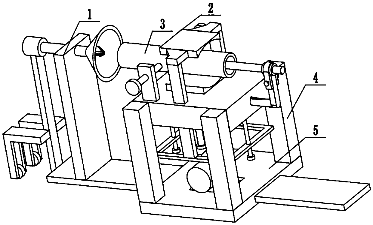
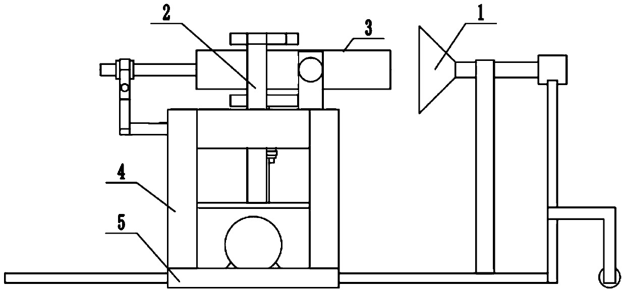
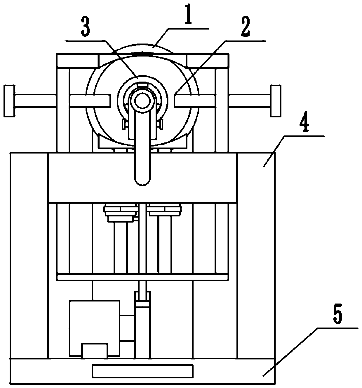
[0038] Combine below figure 1 , 2 3. Description of this embodiment, a steel pipe cut surface grinding treatment device, including cables, cable fixing frames, maintenance track plates, moving mechanisms, rolling brush mechanisms, characterized in that: the number of cable fixing frames is two , respectively located at both ends of the cable, the cable and the cable fixing frame are connected through a gap through the hole, the two ends of the maintenance track plate are respectively fixed above the two cable fixing frames, the moving mechanism and the maintenance track plate are connected through a groove gap, and the maintenance track The plate and the rolling brush mechanism are connected through the gap of the groove, the rolling brush mechanism and the moving mechanism are partially meshed through gears, and the rolling brush mechanism and the moving mechanism are partially fixedly connected.
specific Embodiment approach 2
[0040] Combine below Figure 4 , 5, 6, and 7 illustrate this embodiment, and this embodiment will further illustrate Embodiment 1. The steel pipe grinding device 1 includes moving wheels 1-1, wheel fixing frame 1-2, motor fixing frame A1-3, power motor A1 -4, motor connecting rod 1-5, connecting rod support frame 1-6, grinding mechanism 1-7, moving wheel 1-1 is installed on the wheel fixing frame 1-2 through the shaft activity, and the wheel fixing frame 1-2 is fixedly installed On the motor fixing frame A1-3, the power motor A1-4 is fixedly installed on the motor fixing frame A1-3, the motor connecting rod 1-5 is installed on the output end of the power motor A1-4, and the motor connecting rod 1-5 passes through the bearing Movably installed on the connecting rod support frame 1-6, the grinding mechanism 1-7 is fixedly installed on the connecting rod support frame 1-6, and the connecting rod support frame 1-6 plays the function of supporting the motor connecting rod 1-5 to p...
specific Embodiment approach 3
[0043] Combine below Figure 8 , 9 , 10, 11, and 12 illustrate this embodiment. This embodiment will further illustrate Embodiment 1. The steel pipe clamping device 2 includes a fixed seat 2-1, a keyway 2-2, a connecting key 2-3, and a steel pipe center Alignment mechanism 2-4, top tightening plate 2-5, top tightening screw 2-6, upper pressing plate 2-7, upper pressing plate connecting rod 2-8, driving frame 2-9, adjusting screw 2-10, lower pressing Mechanism 2-11, the keyway 2-2 is arranged on the fixed seat 2-1, the connecting key 2-3 is installed in the keyway 2-2, the steel pipe center alignment mechanism 2-4 is movably connected with the fixed seat 2-1, and the top is tight The plate 2-5 is fixedly installed on the fixed seat 2-1, the top tightening screw rod 2-6 is installed on the top tightening plate 2-5 through threads, and the upper pressing plate 2-7 is fixedly installed on the upper pressing plate connecting rod 2-8. Pressing plate connecting rod 2-8 is slidably ...
PUM
 Abstract
Description
Claims
Application Information
 - R&D
- Intellectual Property
- Life Sciences
- Materials
- Tech Scout
- Unparalleled Data Quality
- Higher Quality Content
- 60% Fewer Hallucinations
Browse by: Latest US Patents, China's latest patents, Technical Efficacy Thesaurus, Application Domain, Technology Topic, Popular Technical Reports.
© 2025 PatSnap. All rights reserved.Legal|Privacy policy|Modern Slavery Act Transparency Statement|Sitemap|About US| Contact US: help@patsnap.com


