
Surface treatment and polishing device for sheet metal processing

A surface treatment and sheet metal technology, which is applied in the field of surface treatment and grinding devices for sheet metal processing, can solve the problems of workers’ personal safety not guaranteed, poor product consistency, harsh working environment, etc., and achieve convenient, fast, accurate and smooth grinding process. Improvement of workpiece applicability and reduction of work cost

Pending Publication Date: 2020-02-14
苏州陈泰利金属科技有限公司
View PDF0 Cites 6 Cited by
  • Summary
  • Abstract
  • Description
  • Claims
  • Application Information

AI Technical Summary

Problems solved by technology

[0003] In the prior art, due to the presence of burrs or corners on the cutting edge of the sheet metal, cracks or gaps will appear on the edge of the stamping part, resulting in the inability to assemble due to the uneven surface, or greatly reducing the aesthetics of the product due to the uneven surface, so sheet metal Grinding in processing has become a crucial process link. Many companies use manual grinding, but manual grinding has the problems of low production efficiency and poor product consistency, and the working environment is harsh, and dust and other pollution are harmful to the health of workers. Relatively large, the personal safety of workers cannot be guaranteed

Method used


Image

  • Surface treatment and polishing device for sheet metal processing
  • Surface treatment and polishing device for sheet metal processing
  • Surface treatment and polishing device for sheet metal processing

Examples


Embodiment Construction

[0023] The following will clearly and completely describe the technical solutions in the embodiments of the present invention with reference to the accompanying drawings in the embodiments of the present invention. Obviously, the described embodiments are only some, not all, embodiments of the present invention. Based on the embodiments of the present invention, all other embodiments obtained by persons of ordinary skill in the art without making creative efforts belong to the protection scope of the present invention.

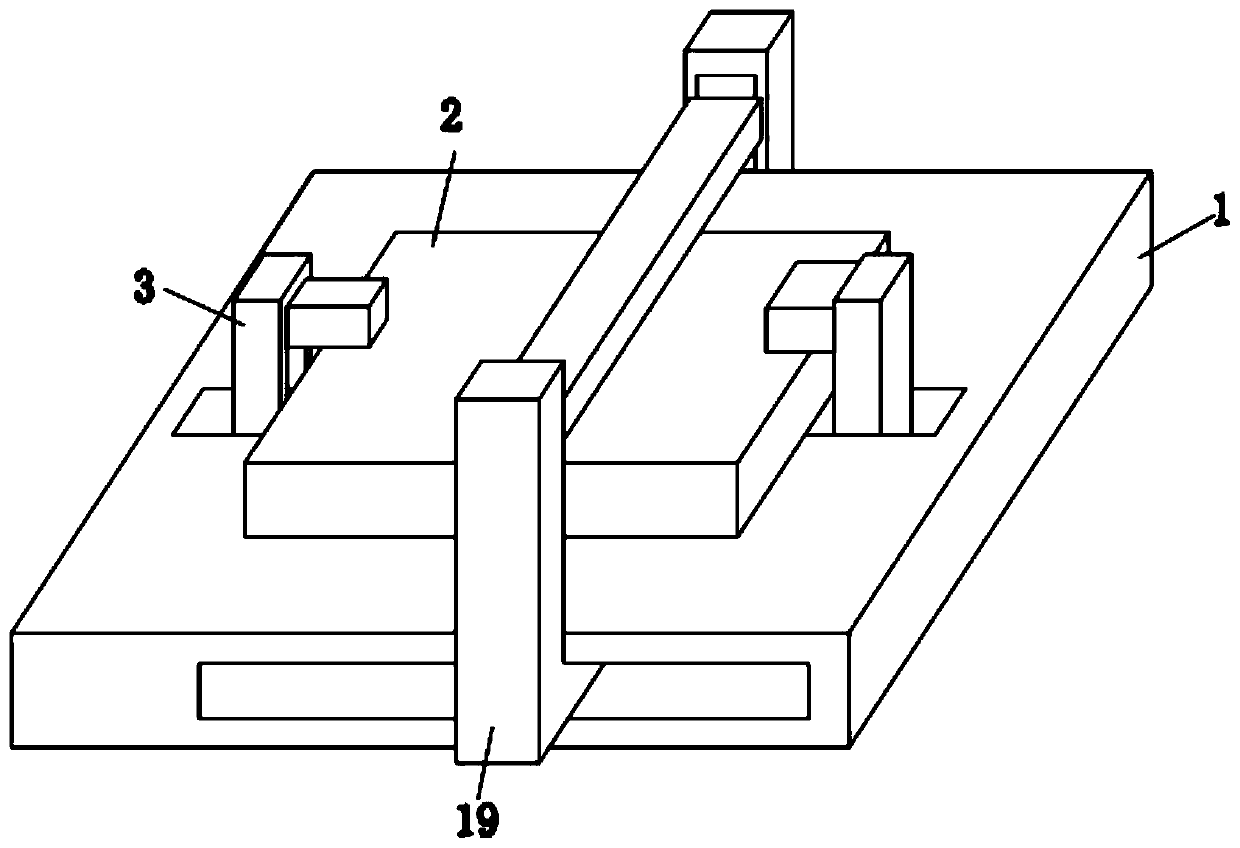
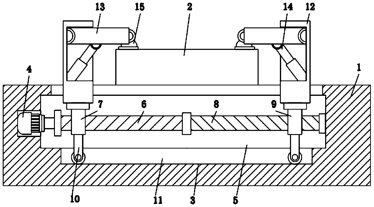
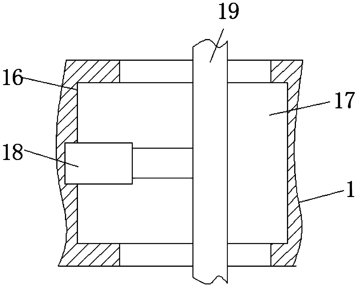
[0024] see Figure 1-4 , a surface treatment grinding device for sheet metal processing, comprising a grinding table 1, a workpiece body 2, a clamping device 3 and a fixed-point grinding device 16, the clamping device 3 is located on the upper surface of the grinding table 1, and the workpiece body 2 Located inside the clamping device 3, the fixed-point grinding device 16 is located inside the grinding table 1;

[0025] The clamping device 3 includes a first ...


PUM


Abstract

The invention discloses a surface treatment and polishing device for sheet metal processing, and relates to the technical field of sheet metal processing. The surface treatment and polishing device for sheet metal processing comprises a grinding table, a workpiece body, a clamping device and a fixed-point grinding device. The clamping device is located on the upper surface of the grinding table. The workpiece body is located in the clamping device. The fixed-point grinding device is located inside the grinding table. According to the surface treatment and polishing device for sheet metal processing, due to the arrangement of the clamping device, a first motor is used for driving two rotating shafts to synchronously rotate, so that two sliding blocks are driven to move face to face or awayfrom each other through cooperation with first electric push rods which drive clamping plates, the surface of the workpiece body is clamped, workpieces with different specifications can be clamped, the workpiece applicability of the device is improved, the workpieces with different specifications can be processed by the device, the situation of purchasing a plurality of sets of grinding devices isavoided, and the working cost is reduced.

Description

technical field [0001] The invention relates to the technical field of sheet metal processing, in particular to a surface treatment and polishing device for sheet metal processing. Background technique [0002] Sheet metal processing is a key technology that sheet metal technicians need to master, and it is also an important process for forming sheet metal products. Sheet metal processing includes traditional cutting, punching, bending and forming methods and process parameters, as well as various cold stamping die structures and process parameters, various equipment working principles and operating methods, and new stamping technology. and new technology. Part metal sheet processing is called sheet metal processing. [0003] In the prior art, due to the presence of burrs or corners on the cutting edge of the sheet metal, cracks or gaps will appear on the edge of the stamping part, resulting in the inability to assemble due to the uneven surface, or greatly reducing the ae...

Claims


Application Information

Patent Timeline
Patent Type & Authority Applications(China)
IPC IPC(8): B24B19/00B24B41/06B24B47/22B24B47/12B24B47/20
CPCB24B19/00B24B41/06B24B47/12B24B47/20B24B47/22
Inventor 包文胜
Owner 苏州陈泰利金属科技有限公司
Learn More