Scrap iron compaction system capable of working continuously

A technology of iron filings and compacting device, applied in the field of parts processing, can solve the problems of unsustainable addition of new iron filings, scattering of iron filings, inconvenience in finishing, etc.

Active Publication Date: 2020-02-14
浙江阳力钢结构股份有限公司
View PDF8 Cites 4 Cited by
  • Summary
  • Abstract
  • Description
  • Claims
  • Application Information

AI Technical Summary

Problems solved by technology

[0003] Machinery processing plants will produce a large amount of scrap iron scraps during the production process, scrap iron scraps have a high recycling value, and scrap iron scraps need to be compacted during recycling to facilitate transportation. When compacting iron scraps, It is necessary to flatten the iron filings with a plate such as a pressing plate, so that the iron filings can be processed into a regular shape. During the flattening of the iron filings, new iron filings cannot be continuously added. The transportation and flattening of the iron filings need to be handled separately. The flattening and transportation of swarf are carried out simultaneously, and some iron shavings will still be scattered near the processing table, causing inconvenience in sorting

Method used


Image

  • Scrap iron compaction system capable of working continuously
  • Scrap iron compaction system capable of working continuously
  • Scrap iron compaction system capable of working continuously

Examples


Embodiment Construction

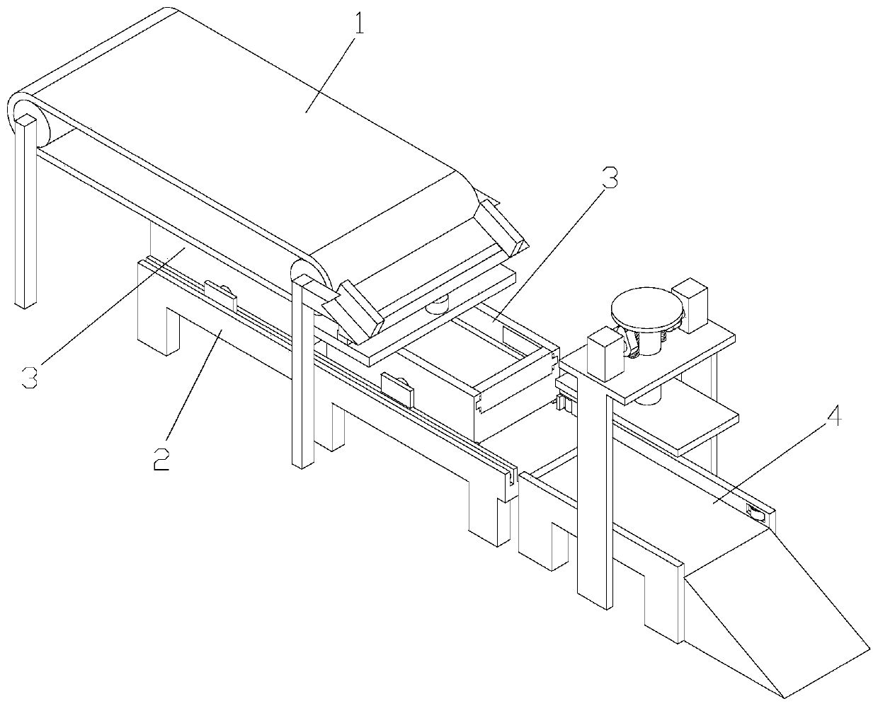
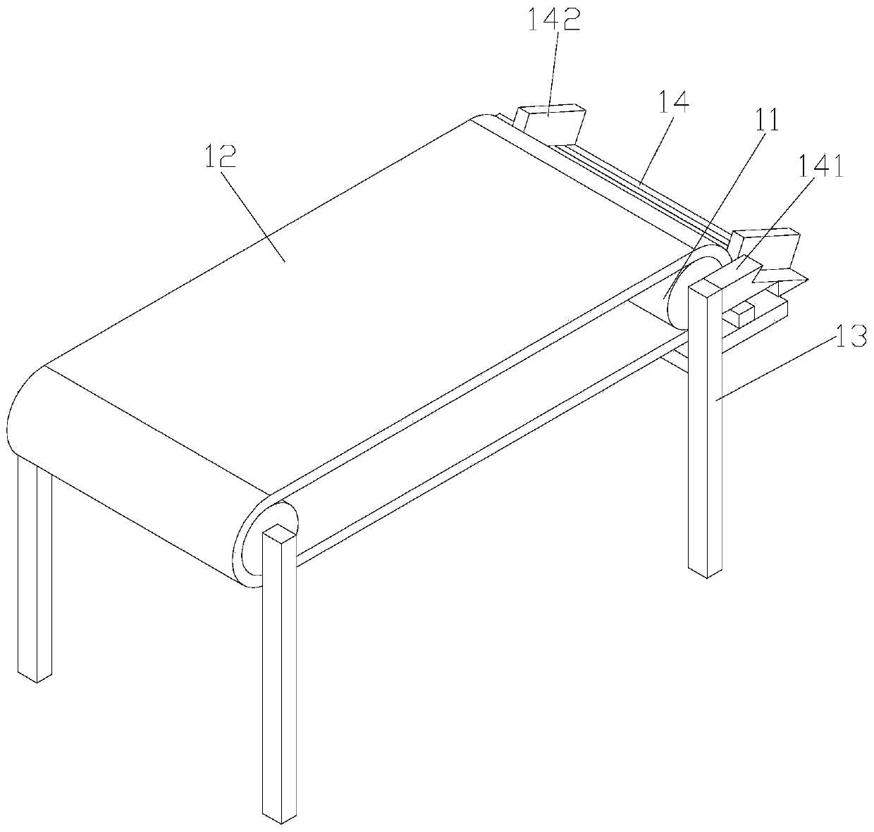
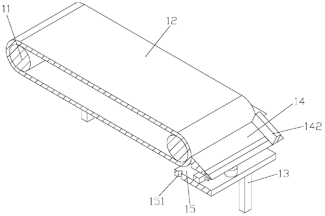
[0031] Such as Figure 1-18 As shown, a continuously working chip compaction system includes a conveying device 1, a receiving device, a conveying device 2 and a compacting device 4. The conveying device 1 includes a first transmission roller 11, which is sleeved on The first conveyor belt 12 on the first transmission roller 11 and the first support feet 13 located on both sides of the first transmission roller 11, the first transmission roller is two, the first conveyor belt is fixed, the first The driving roller is connected with a first driving motor, and the first driving motor provides rotational power for the first driving roller; the conveying device 2 is arranged below the first conveyor belt 12, and the material receiving device is arranged on the conveying device 2 Above, the material receiving device includes a material receiving plate 3, a first baffle plate 31 and a second baffle plate 32 arranged on the material receiving plate 3, the first baffle plate and the s...


PUM


Abstract

The invention discloses a scrap iron compaction system capable of working continuously. The scrap iron compaction system comprises a material conveying device, material receiving devices, a transporter and a compaction device. The material conveying device comprises first transmission rollers, a first conveying belt arranged on the first transmission rollers in a sleeving manner and first supporting feet arranged on the two sides of the first transmission rollers. The transporter is arranged below the first conveying belt. The material receiving devices are arranged on the transporter. Fifth connecting rods are arranged on the first supporting feet. A scraping plate is arranged on the fifth connecting rods and is provided with a through cavity, and a ninth baffle capable of doing lifting motion is arranged in the through cavity in a penetrating manner. When the material receiving devices move to the position of the compaction device and the material receiving devices are not replaced,the ninth baffle rises in the through cavity, a stop function is achieved on scrap iron on the scraping plate under the action of the ninth baffle, the scrap iron is prevented from continuously falling down, part of scrap iron stays on the scraping plate temporarily, and the situation that the scrap iron directly falls off to cause clearing inconvenience is avoided.

Description

technical field [0001] The invention belongs to the technical field of parts processing, and in particular relates to a continuously working iron scrap compacting system. Background technique [0002] Machining refers to the process of changing the shape or performance of a workpiece through a mechanical device. According to the difference in processing method, it can be divided into cutting processing and pressure processing. The production process of a machine refers to the entire process of making a product from raw materials (or semi-finished products). For machine production, it includes transportation and storage of raw materials, production preparation, blank manufacturing, processing and heat treatment of parts, product assembly, debugging, painting and packaging, etc. The content of the production process is very extensive. Modern enterprises use the principles and methods of systems engineering to organize and guide production, and regard the production process a...

Claims


Application Information

Patent Timeline
Patent Type & Authority Applications(China)
IPC IPC(8): B30B9/32B30B15/00B30B15/30B30B15/32
CPCB30B9/32B30B15/00B30B15/30B30B15/32
Inventor 张飞金国军
Owner 浙江阳力钢结构股份有限公司
Why Eureka
Try Eureka