
Automatic detection method and device for state of liquid monitoring sensor

An automatic detection device and a technology for monitoring sensors, applied in the field of monitoring, can solve problems such as low maintenance efficiency, inability to achieve sensor contamination, failure, and increased maintenance procedures, and achieve the effect of efficient and accurate detection

Pending Publication Date: 2020-02-14
BEIJING TENGINE INNOVATION INSTR
View PDF0 Cites 0 Cited by
  • Summary
  • Abstract
  • Description
  • Claims
  • Application Information

AI Technical Summary

Problems solved by technology

However, these maintenance methods are traditionally operated manually, which cannot automatically identify fault states such as sensor contamination and failure.
[0005] Using the above manual maintenance method to maintain the status of the sensor will bring the following problems: 1. If the sensor is contaminated or drifted between the two maintenances, the measurement result will be inaccurate, but it cannot be found in time. 2. In the water quality The monitoring process cannot automatically maintain the working status of the sensor, and additional maintenance procedures are required, resulting in low maintenance efficiency. 3. Manual maintenance requires high costs, and it is difficult to achieve an optimal balance between data accuracy and sensor maintenance costs

Method used


Image

  • Automatic detection method and device for state of liquid monitoring sensor
  • Automatic detection method and device for state of liquid monitoring sensor
  • Automatic detection method and device for state of liquid monitoring sensor

Examples


Embodiment 1

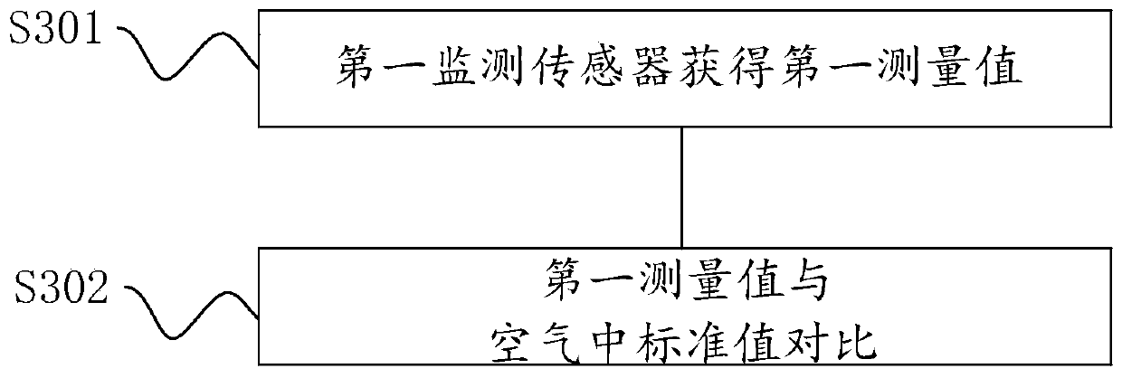
[0080] see image 3 with Figure 5 , the monitoring sensor used in this embodiment is one or both of the dissolved oxygen sensor 121 or the conductivity sensor 122 . The method for detecting the state of the monitoring sensor of this embodiment is as follows:

[0081] Step S301, the dissolved oxygen sensor or the conductivity sensor measures the dissolved oxygen or conductivity of the air to obtain the first measurement value, specifically, by starting the valve to control the sensor to be in the air, the liquid level of the liquid is at the first level F1, and the sensor is The parameter of the air is measured, and the obtained measured value is the first measured value. Wherein, the first liquid level F1 is any position where the monitoring sensor is completely separated from the liquid.

[0082] In step S302, the first measured value is compared with the standard value of dissolved oxygen and / or conductivity in the air, and the dissolved oxygen or conductivity in the air...

Embodiment 2

[0086] see Figure 4 , Figure 7a with Figure 7b , the monitoring sensor used in this embodiment is the turbidity sensor 123 . The method for detecting the state of the monitoring sensor of this embodiment is as follows:

[0087] In step S301', the turbidity sensor obtains a first measurement value, specifically, by starting the valve to control the liquid to be at the first liquid level, that is, the intersection point of the turbidity sensor and measuring the first measurement value. Specifically, the first liquid level is the position of the intersection of the emitting light path and the 90-degree receiving light path of the turbidity sensor, and the turbidity sensor is in the standard medium.

[0088] Step S302', the turbidity sensor is located at the second liquid level F2, and the turbidity of the air is measured to obtain the second measured value, specifically, the liquid level is controlled to continue to drop by starting the valve until the liquid level is below...

Embodiment 3

[0095] The monitoring sensors used in this embodiment are dissolved oxygen sensors, conductivity sensors and pH sensors. The method for detecting the state of the monitoring sensor of this embodiment is as follows:

[0096] Because the dissolved oxygen sensor, conductivity sensor and pH sensor all need temperature compensation, they all have temperature measurement function. Before detecting the state of the sensor, set the dissolved oxygen sensor, the conductivity sensor and the pH sensor in the liquid at the same time to measure the temperature of the liquid at the same time; all generate temperature measurement values, compare each generated temperature measurement value, and all differences When the values ​​are all lower than the set temperature difference d2t, the states of the three sensors are normal. Otherwise, the sensor fails, where d2t can be set according to the actual parameters of the sensor, specifically, the set temperature difference is the one with the high...


PUM


Abstract

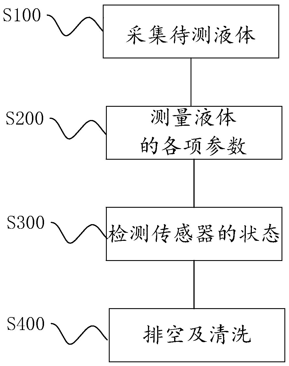
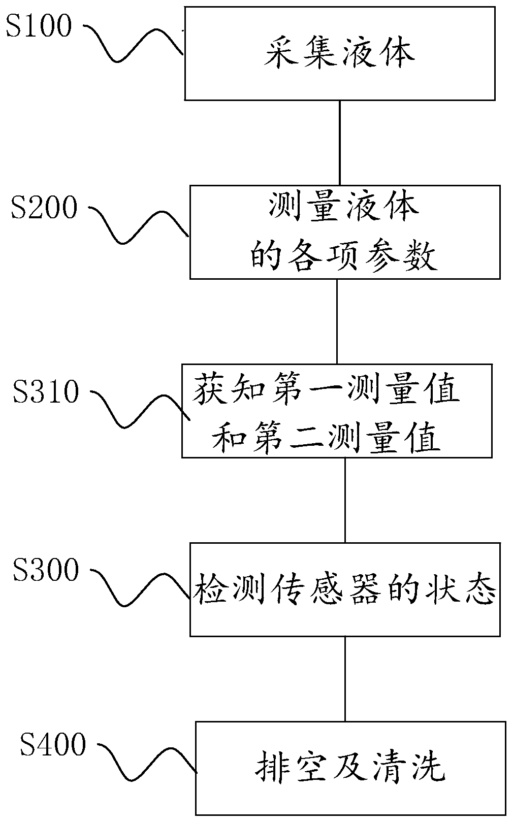
The invention discloses an automatic detection method and device for the state of a liquid monitoring sensor. The method comprises the steps: collecting liquid; to be specific, collecting the liquid into a flow cell, and enabling at least one monitoring sensor to be arranged in the flow cell in the liquid; measuring various parameters of the liquid; to be specific, correspondingly measuring various parameters in the liquid by the at least one monitoring sensor; detecting the state of the sensor; to be specific, testing the parameter at the moment of being at a first liquid level of the liquidas a first measuring value by the at least one monitoring sensor, testing the parameter at the moment of being at a second liquid level of the liquid as a second measuring value by the at least one monitoring sensor, comparing the first measuring value with the second measuring value or comparing the first measuring value with a standard value of a standard medium, and determining the state of theat least one sensor according to the comparison result; and carrying out exhausting and cleaning; to be specific, exhausting the liquid in the flow cell and cleaning the flow cell. Therefore, problems of low maintenance efficiency and high cost caused by manual maintenance of the state of the liquid monitoring sensor in the prior art are solved.

Description

technical field [0001] The invention relates to the technical field of monitoring, in particular to an automatic detection method and device for the state of a liquid monitoring sensor. Background technique [0002] As a kind of liquid monitoring sensor, the water quality monitoring sensor is widely used in the field of water quality monitoring for signal acquisition. There are many types of water quality monitoring sensors at present, such as dissolved oxygen, turbidity, pH, conductivity, temperature, UV method COD sensor, spectral multi-parameter and other water quality monitoring sensors. In addition to being used for water quality monitoring alone, water quality monitoring sensors can also be integrated with other instruments (cabinet analyzers, etc.) to collect various parameters for water quality monitoring, and the application fields are very wide. [0003] The existing sensor monitors the water quality by setting the sensor in the sampling pool. When water quality m...

Claims


Application Information

Patent Timeline
Patent Type & Authority Applications(China)
IPC IPC(8): G01N33/18G01R35/00G01N27/06
CPCG01N33/18G01R35/00G01N27/06
Inventor 任宏刚樊昕
Owner BEIJING TENGINE INNOVATION INSTR
Learn More