Method for predicting and optimizing abrasion of valve in pneumatic conveying system

A technology of a pneumatic conveying system and an optimization method, applied in the field of valves, can solve the problems of high gas velocity, particle erosion and wear, consuming a lot of manpower, material and financial resources, etc.

Pending Publication Date: 2020-02-14
ZHEJIANG SCI-TECH UNIV
View PDF3 Cites 5 Cited by
  • Summary
  • Abstract
  • Description
  • Claims
  • Application Information

AI Technical Summary

Problems solved by technology

The valve is a kind of gas control device in the pneumatic conveying pipeline system. During the use of the valve, the existence of solid particles will cause two problems: one is the problem of two-phase flow; the other is the problem of particle erosion wear
During the opening process of the valve, due to the high pressure in front of the valve, the velocity of the gas is high, and the medium in front of the valve is a fluidized gas-solid two-phase mixture, and there is a large amount of particle erosion during the transient process of opening.
[0003] Existing valve wear prediction and optimization usually use experimental methods for actual measurement, but the experimental period of this actual measurement method is very long, the time cost is very high, and it will also consume a lot of manpower, material and financial resources. There are many uncertain factors, which will have a great impact on the experimental results of wear, resulting in inaccurate experimental results.

Method used


Image

  • Method for predicting and optimizing abrasion of valve in pneumatic conveying system
  • Method for predicting and optimizing abrasion of valve in pneumatic conveying system
  • Method for predicting and optimizing abrasion of valve in pneumatic conveying system

Examples


Embodiment Construction

[0062] Below in conjunction with the accompanying drawings, the present invention will be further described by taking a ball valve as an example.

[0063] Embodiments of the present invention and its implementation process are as follows:

[0064] Step 1: Obtain the ball valve pipeline model

[0065] 1. Establish a ball valve model

[0066] According to the actual structure in engineering application, the pipe diameter at the valve is D, use SolidWorks software or other 3D modeling software to carry out 3D modeling of the ball valve on the pipeline to obtain the 3D model of the ball valve;

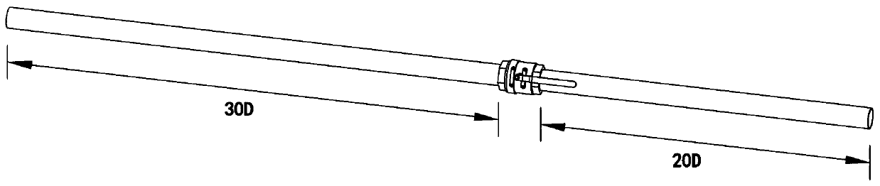
[0067] 2. Establish the pipeline structure at the ball valve

[0068] Extend the upstream pipeline of the ball valve in the 3D model by 30D; extend the downstream pipeline to 20D to obtain the pipeline structure of the ball valve, such as image 3 shown;

[0069] 3. Simplify the structure

[0070] According to the function and characteristics of the ball valve, the structure of the ba...


PUM


Abstract

The invention discloses a method for predicting and optimizing abrasion of a valve in a pneumatic conveying system. Establishing a valve pipeline model, and extracting a gas domain to obtain a flow channel model; meshing the flow channel model, and dividing the flow channel model into a plurality of sets of flow channel mesh models with different mesh numbers; calculating a flow coefficient of a flow channel in the model, comparing flow coefficient results of the flow channel mesh models, and selecting one set of flow channel mesh model from the flow coefficient results; flow field analysis isconducted on the flow channel grid model, a speed cloud chart, a particle distribution cloud chart and an abrasion cloud chart are obtained respectively, and the flowing situation of gas and solid particles in the valve and the abrasion situation caused to the interior of the valve are analyzed. According to the method, the two-phase flow state of gas and solid particles in the valve can be simulated, the abrasion of the particles to the valve in the two-phase flow state is predicted, and the structure of the valve is optimally designed according to the abrasion condition of the valve.

Description

technical field [0001] The invention belongs to the technical field of valves and relates to a method for predicting and optimizing valve wear in a pneumatic conveying system, in particular to research on wear of valves in the field of dilute-phase pneumatic conveying. Background technique [0002] Pneumatic conveying is a conveying method that uses airflow at a certain pressure and a certain speed to convey dry powder and granular materials in pipelines. It widely exists in various industrial fields, such as the transportation of fly ash and pulverized coal in power plants, the transportation of fertilizer granules in the chemical industry, the transportation of flour in the food industry, the transportation of metal powder in foundries, and the transportation of pharmaceutical granules in pharmaceutical factories, etc. . In dilute phase transportation, the gas velocity is generally 10-40m / s, the solid-gas ratio is generally less than 5, and solid particles move in the pip...

Claims


Application Information

Patent Timeline
Patent Type & Authority Applications(China)
IPC IPC(8): G06F30/17G06F30/18G06F30/28G06Q10/04
CPCG06Q10/04
Inventor 林哲孙希望周萱艺陈德胜朱祖超
Owner ZHEJIANG SCI-TECH UNIV
Why Eureka
Try Eureka