Indication value pattern positioning and segmentation method in test/detection/calibration/verification

A technology of indicating value and pattern, applied in the field of radiation dose verification, to achieve the effect of speeding up the calculation

Pending Publication Date: 2020-02-14
中国测试技术研究院辐射研究所
View PDF15 Cites 0 Cited by
  • Summary
  • Abstract
  • Description
  • Claims
  • Application Information

AI Technical Summary

Problems solved by technology

[0008] (1) It may be necessary (and possible) to obtain the indication value of the instrum

Method used


Image

  • Indication value pattern positioning and segmentation method in test/detection/calibration/verification
  • Indication value pattern positioning and segmentation method in test/detection/calibration/verification
  • Indication value pattern positioning and segmentation method in test/detection/calibration/verification

Examples


Embodiment 1

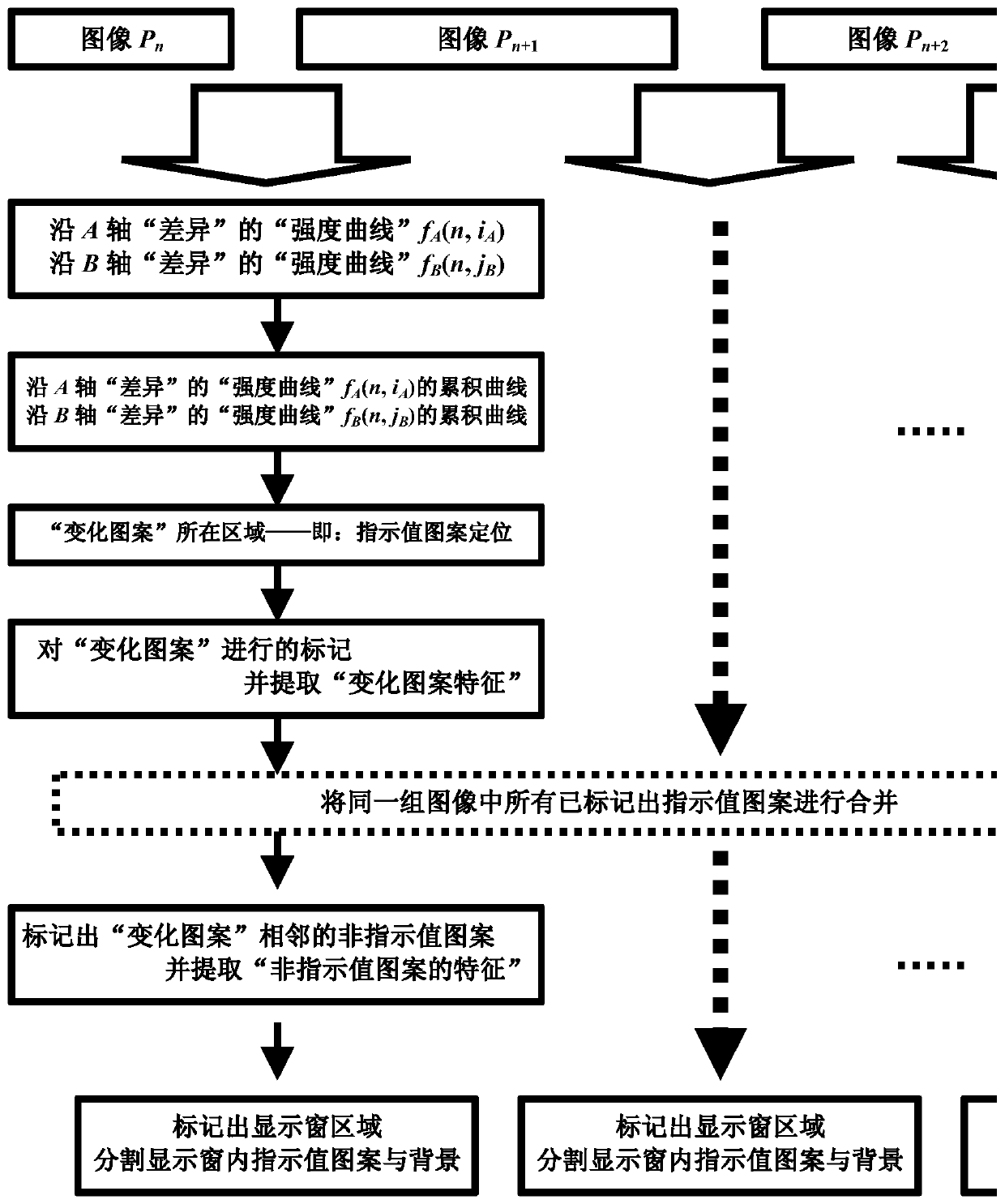
[0083] In the test / detection / calibration / verification, the indicator value pattern positioning and segmentation method includes the following steps: such as figure 1 Shown, below in conjunction with embodiment the patent of the present invention is described in further detail;

[0084] S1. "Under the same conditions" use an image acquisition device to collect a set of images containing the indicated value of the instrument to be tested;

[0085] A group of images includes at least 2 images, one of which is the image (A) of the indicated value of the tested instrument before the impact is applied or changed, and the other image is the image of the tested instrument after the influence is applied or changed. The image (B) of the indicated value of the detected instrument when the influence amount is applied, or in the process of applying the influence amount or changing the influence amount, or after applying the influence amount or changing the influence amount;

[0086] The "...

example 1

[0130] Example 1: When the dot matrix of some green-yellow LCD liquid crystal displays flips and changes, the change value of the blue component (B) is small, so when calculating the gray scale, the weight coefficient of the blue component (B) is taken as "0" (k b =0), the "feature quantity" of the pixel is represented by formula (8):

[0131] x n (i, j) = r n (i,j)+g n (i,j) (8)

example 2

[0132] Example 2: As shown in Figure 8, the white background of a red alcohol thermometer, in Figure 8 (806) the red component (R) red alcohol column is difficult to separate from the background next to it and the value is slightly higher than the background next to it, Comparing the (804) blue component (B) in Figure 8 and the (805) green component (G) in Figure 8, the red alcohol column is very different from the background. As an optimal technical solution, the "feature value" of the pixel is calculated using the formula (9 ) indicates that, as shown in (807) in Figure 8, formula (9) also brings the advantage of increasing the difference between the red alcohol column and the background by 2 times.

[0133] x n (i,j)=g n (i,j)+b n (i,j) (9)


PUM


Abstract

The invention discloses an indication value pattern positioning and segmenting method in test/detection/calibration/verification. Non-specific display, under the same condition, an image collection device is used to acquire an image of a detected instrument accommodating an indication value. Time-dependent change and invariant difference of'primitives' in an image and correlation information between adjacent'primitives' are utilized; accumulating the'intensity curve 'of the'difference value' of the'characteristic quantity 'of'primitives'; obtaining an area where the change indication value pattern is located, i.e., obtaining the change indication value pattern; positioning an indication value pattern and a display window; by using the method, an indication value pattern position and a display window position are automatically searched; wherein the change indication value pattern is separated from the background region, so that the indication value pattern possibly having no change in the region where the change indication value pattern is located is separated from the background region, and finally, all indication value patterns of the display window are expanded to be separated from the background region.

Description

technical field [0001] The invention relates to radiation dose verification, and mainly relates to a method for positioning and dividing an indication value pattern in testing / detection / calibration / verification. Background technique [0002] The test / detection / calibration / verification mentioned in the name of the present invention means four kinds of objects, that is, the four kinds of objects of test, detection, calibration and verification respectively, not one test / detection / calibration / verification object. [0003] In the prior art, more and more devices and methods obtain the display graphics of the tested meters, and then convert the displayed graphics into ASCII-coded meter readings that can be processed by a computer and generate corresponding reports. [0004] For example: for pointer watches, the relatively representative invention patent 2004101042084 "A Method for Automatic Recognition and Reading of Pointer Watches" obtains the pointer dial image, and then inter...

Claims


Application Information

Patent Timeline
IPC IPC(8): G06K9/32G06K9/46
CPCG06V20/62G06V10/44G06V2201/03G06V30/10Y02E30/30
Inventor 刘志宏于兵沈义文王歆鑫但玉娟
Owner 中国测试技术研究院辐射研究所
Why Eureka
Try Eureka