Infrared image stripe removal method, processing equipment and storage device

An infrared image and horizontal stripe technology, applied in the field of thermal imaging, can solve the problems of difficult hardware implementation, incomplete output circuit bias voltage, and inability to filter random stripes, etc., to achieve the effect of maintaining clarity

Active Publication Date: 2022-06-07
浙江华感科技有限公司
View PDF6 Cites 0 Cited by
  • Summary
  • Abstract
  • Description
  • Claims
  • Application Information

AI Technical Summary

Problems solved by technology

However, due to the current technological level, the output circuit of the infrared focal plane array usually shares the same output circuit with pixels in the same row (or column), and the bias voltage of the output circuit is not exactly the same, so that different sensors on the infrared focal plane array are opposite to each other. The same infrared radiation will produce different output signals, making a kind of streaky non-uniform noise in the infrared image
[0003] In the existing design, the calibration-based correction method cannot update the parameters in real time, and it needs to assume that the parameters remain unchanged for a long period of time between two consecutive calibrations, while the bias voltage of the output circuit of the infrared focal plane array changes rapidly. Therefore, noise cannot be effectively eliminated; although the method based on scene correction can update parameters in real time, it takes a long time to converge, and the use of long-term image sequences may cause "smearing" phenomenon, which cannot effectively eliminate noise; frequency domain filtering is used method, it is effective for periodic stripes, but it cannot filter random stripes, and it is not easy to implement in hardware; in addition, the mean value of the current row is estimated by using the mean variance of adjacent rows, and then the original mean value of the current row is replaced by the estimated row mean value. This method It is only effective for images with a small range of temperature changes in the scene. For images with large temperature differences, the error in estimating the row mean with the mean variance of adjacent rows is large, and additional stripes will be introduced instead.

Method used


Image

  • Infrared image stripe removal method, processing equipment and storage device
  • Infrared image stripe removal method, processing equipment and storage device
  • Infrared image stripe removal method, processing equipment and storage device

Examples


Embodiment Construction

[0022] The solutions of the embodiments of the present application will be described in detail below with reference to the accompanying drawings.

[0023] In the following description, for purposes of illustration and not limitation, specific details such as specific system structures, interfaces, techniques, etc. are set forth in order to provide a thorough understanding of the present application.

[0024] The terms "system" and "network" are often used interchangeably herein. The term "and / or" in this article is only an association relationship to describe the associated objects, indicating that there can be three kinds of relationships, for example, A and / or B, it can mean that A exists alone, A and B exist at the same time, and A and B exist independently B these three cases. In addition, the character " / " in this document generally indicates that the related objects are an "or" relationship. Also, "multiple" herein means two or more than two.

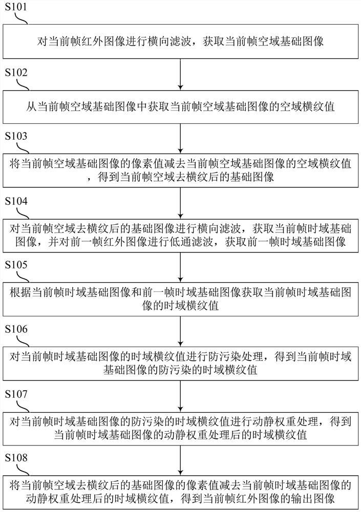
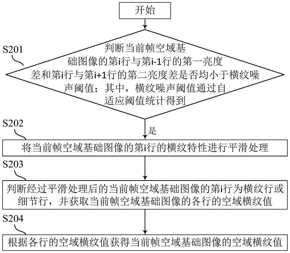
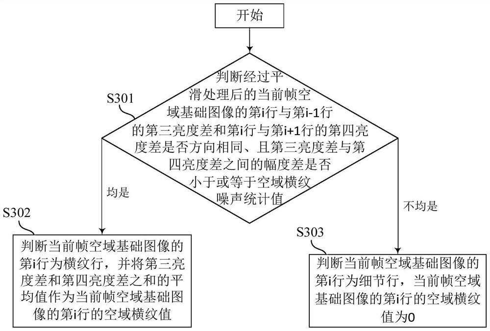
[0025] see figure 1 , ...


PUM


Abstract

The application discloses a method for removing horizontal stripes on an infrared image, a processing device and a storage device. Wherein, the infrared image de-striping processing method includes: obtaining the spatial stripe value of the current frame spatial basic image of the current frame infrared image, subtracting the spatial horizontal stripe value of the current frame spatial basic image from the pixel value of the current frame spatial basic image, Obtain the basic image of the current frame after removing stripes in the spatial domain; obtain the current frame time domain basic image and the previous frame time domain basic image, and obtain the current frame time domain basic image according to the current frame time domain basic image and the previous frame time domain basic image The time-domain horizontal stripe value; and anti-pollution processing and dynamic and static weight processing, the pixel value of the basic image after the current frame is subtracted from the current frame time-domain basic image after the anti-pollution processing and dynamic and static weight processing. domain horizontal stripe value to get the output image of the current frame infrared image. The above solution can make the output image have better definition and no smear.

Description

technical field [0001] The present application relates to the technical field of thermal imaging, and in particular, to an infrared image de-stripe processing method, processing equipment and storage device. Background technique [0002] Infrared sensors can convert infrared light into electrical signals and are the core components of infrared imaging equipment. Infrared sensors based on infrared focal plane arrays are the mainstream development direction of infrared sensors because of their small size, low cost, and high sensitivity. However, due to the current technology level, the output circuit of the infrared focal plane array is usually the same row (or column) of pixels sharing the same output circuit, and the output circuit bias voltage is not exactly the same, so different sensors on the infrared focal plane array The same infrared radiation produces different output signals, resulting in a streak-like non-uniform noise in the infrared image. [0003] In the exist...

Claims


Application Information

Patent Timeline
Patent Type & Authority Patents(China)
IPC IPC(8): G06T5/00
CPCG06T5/002G06T2207/10048G06T2207/20024
Inventor 郁军军胡文龙方伟
Owner 浙江华感科技有限公司
Why Eureka
Try Eureka