Automatic feeding and discharging device

A technology of automatic loading and unloading, hopper, applied in the direction of feeding device, peeling device, positioning device, etc., can solve the problems of low efficiency of manual loading and unloading, complex structure of automatic loading and unloading, and achieve the effect of improving production efficiency

Active Publication Date: 2020-02-18
重庆理工清研凌创测控科技有限公司
View PDF5 Cites 4 Cited by
  • Summary
  • Abstract
  • Description
  • Claims
  • Application Information

AI Technical Summary

Problems solved by technology

[0004] Aiming at the deficiencies of the above-mentioned prior art, the present invention provides an automatic loading and unloading device, which s

Method used


Image

  • Automatic feeding and discharging device
  • Automatic feeding and discharging device
  • Automatic feeding and discharging device

Examples


Embodiment Construction

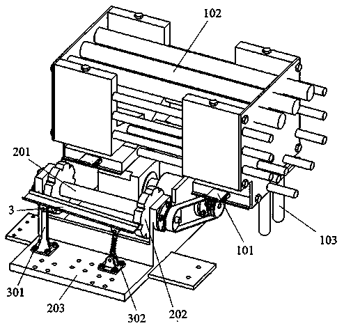
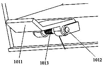
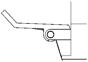
[0022] refer to figure 1 As shown, the automatic loading and unloading device includes a hopper 102. The inner bottom of the hopper 102 is provided with a slope surface, and the side wall of the hopper 102 is provided with a feed opening connected to the lower end of the slope surface. The front end of the paddle 101 is upturned to form a catch 1011, and the rear end of the paddle 101 is rotatably connected to the horizontal shaft 1012, and the horizontal shaft 1012 is connected to the paddle bracket fixed on the outer side of the bottom of the hopper 102; the bottom surface of the paddle is connected to the outer side of the bottom of the hopper An elastic reset mechanism is arranged between them, and the elastic reset mechanism makes the paddle 101 automatically flip up after being pressed downwards; a rotary table 2 is set under the paddle 101, and a turntable motor is arranged on the rotary table 2 and is parallel to the feeding port. The turntable shaft 201, the turntable...


PUM


Abstract

The invention discloses an automatic feeding and discharging device. The automatic feeding and discharging device comprises a hopper. A slope is arranged at the inner bottom of the hopper. A materialport communicating with the lower end of the slope is formed in the side wall of the hopper, and a shifting piece which can rotate up and down is arranged below the material port. An elastic reset mechanism is arranged between the bottom surface of the shifting piece and the outer side face of the bottom of the hopper. A rotary workbench is arranged below the shifting piece. A rotary table motor and a rotary table shaft parallel to the material port are arranged on the rotary workbench. Rotary tables are fixedly connected to the two ends of the rotary table shaft. When the rotary table shaft drives the rotary tables to rotate outwards, pipes falling into clamping grooves of the rotary tables form the shifting piece by self gravity can sequentially reach a feeding station, a machining station and a discharging station. By the adoption of the automatic feeding and discharging device, the technical problems that in the prior art, the efficiency of manual feeding and discharging is low, and an automatic feeding and discharging structure is complete are solved.

Description

technical field [0001] The invention belongs to the field of mechanical processing equipment, in particular to a device for loading and unloading pipe materials such as steel pipes and copper pipes. Background technique [0002] Flaring machines are widely used in the field of machinery manufacturing. The wall thickness of the pipes used in the air-conditioning home appliance industry is relatively thin, generally between 1-1.5mm. In this field, a special pipe flaring machine is generally used for flaring. Due to the thin wall thickness of the pipe and the good ductility of copper, it can be easily expanded by using the punch reaming method. Due to the advantages of high efficiency and good flaring quality, the pipe flaring machine has been widely used in the air-conditioning industry. At present, there are many manufacturers specializing in the design and production of various types of pipe flaring machines. Existing pipe flaring machines have different degrees of automat...

Claims


Application Information

Patent Timeline
IPC IPC(8): B21D41/02B21D43/16B21D43/14B21D45/00
CPCB21D41/02B21D43/006B21D43/026B21D43/14B21D43/16B21D45/00
Inventor 黄金熊洋胡荣丽黄飞翔敖磊
Owner 重庆理工清研凌创测控科技有限公司
Why Eureka
Try Eureka