
twist drill

A twist drill and drill tip technology, which is applied in the fields of metal cutting and metal cutting tools, can solve the problems of slow speed, low efficiency, and difficulty in drilling and positioning of twist drills.

Active Publication Date: 2021-07-06
上海钰工工具有限公司
View PDF7 Cites 1 Cited by
  • Summary
  • Abstract
  • Description
  • Claims
  • Application Information

AI Technical Summary

Problems solved by technology

[0004] In order to solve the technical problems of difficult positioning, slow speed and low efficiency of twist drills in the prior art, the application proposes the following technical solutions

Method used


Image

  • twist drill
  • twist drill
  • twist drill

Examples


Embodiment Construction

[0051] The following will clearly and completely describe the technical solutions in the embodiments of the present application with reference to the accompanying drawings in the embodiments of the present application. Obviously, the described embodiments are only part of the embodiments of the present application, not all of them. Based on the embodiments in this application, all other embodiments obtained by persons of ordinary skill in the art without creative efforts fall within the scope of protection of this application.

[0052] It should be noted that all directional indications (such as up, down, left, right, front, back...) in the embodiments of the present application are only used to explain the relationship between the components in a certain posture (as shown in the drawings). Relative positional relationship, movement conditions, etc., if the specific posture changes, the directional indication will also change accordingly.

[0053] In addition, the descriptions i...


PUM


Abstract

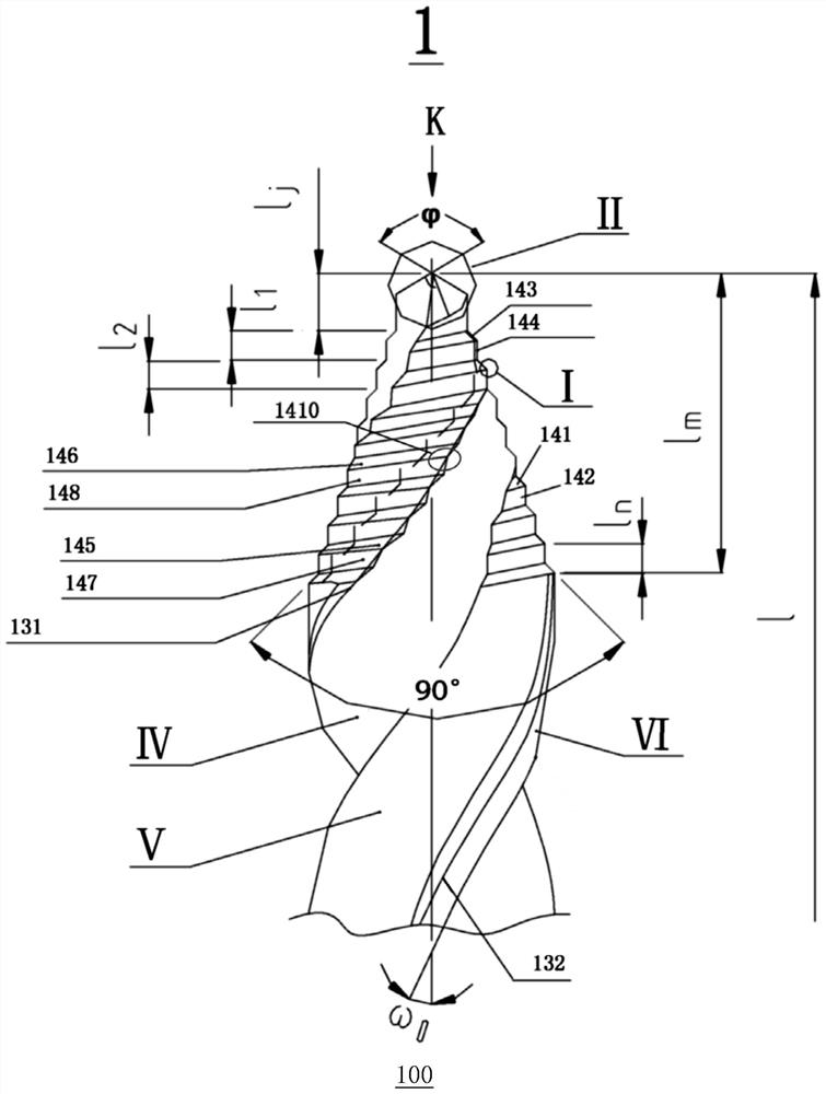
The present application discloses a twist drill. A cone part is arranged at the front end of the working part, and the outer surface of the working part is provided with a spiral groove for shunting and cutting chips; the outer surface of the cone part is provided with a diameter from the front end to the tail end. Multiple groups of composite cutting edges that become larger in sequence, and the tip of the cone part is provided with a drill point top edge. When in use, the top edge of the drill point can play the role of initial positioning, and the cutting process is completed by the top edge of the drill point and multiple sets of composite cutting edges. Since the diameters of the top edge of the drill tip and multiple sets of composite cutting edges become larger from the tip to the tail, it can be said that the cutting object allowance is reasonably distributed according to the diameter of the drilling hole, and the amount of cutting objects is gradually decomposed and cut, and the cutting force is at the level of each cutting edge. The upper surface is dispersed, the reaction force on each cutting edge is also reduced, the burr on the edge of the knife is less, the drilling process is smoother, and the drilling efficiency is higher.

Description

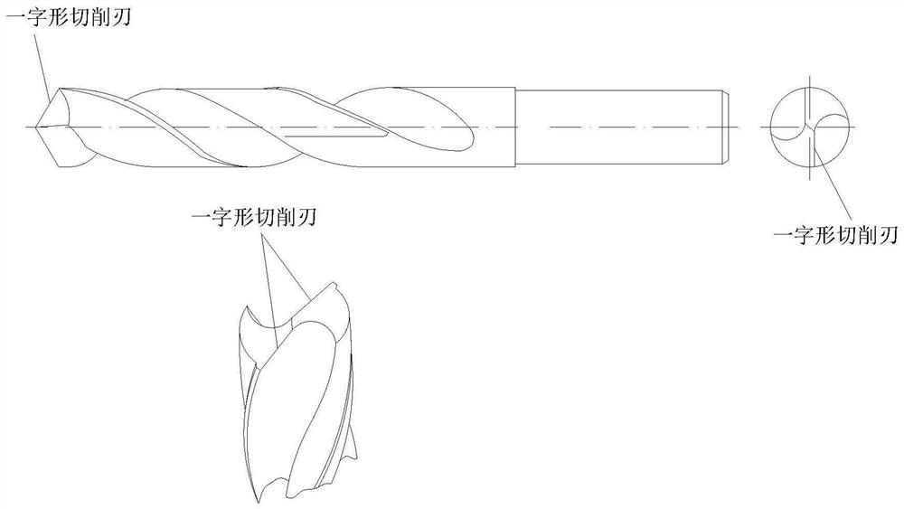
technical field [0001] The present application relates to the technical field of metal cutting processing and metal cutting tools, in particular to twist drills. Background technique [0002] figure 1 It is a schematic diagram of a conventional structure twist drill. figure 1 The left side of the upper middle row is the front view of the twist drill, and the right side is the top view of the drill tip. figure 1 The next line in the middle is the 3D stereogram of the partially truncated twist drill. Twist drills are mostly used in workplaces far away from other metal cutting machine tools such as drill presses. Hand-held electric tools are used for drilling operations. Limited by human arm strength and power tool power, the efficiency of existing twist drills in drilling It is subject to great constraints-difficult punching and positioning, slow speed, and low efficiency. [0003] figure 1 The twist drill with the conventional structure shown in the diagram shows the ana...

Claims


Application Information

Patent Timeline
Patent Type & Authority Patents(China)
IPC IPC(8): B23B51/02
CPCB23B51/02B23B2251/04B23B2251/18B23B51/009
Inventor 王宏嘉
Owner 上海钰工工具有限公司
Learn More