
Electrolytic machining tool enabling flow field period fluctuation and method

A technology for machining tools and flow fields, applied in the field of electrolytic machining tools, can solve problems such as complex equipment, and achieve the effects of improving the quality of the machined surface, improving the stability and uniformity, and improving the stability.

Active Publication Date: 2020-02-18
NANJING UNIV OF AERONAUTICS & ASTRONAUTICS
View PDF9 Cites 3 Cited by
  • Summary
  • Abstract
  • Description
  • Claims
  • Application Information

AI Technical Summary

Problems solved by technology

However, both ultrasonic electrolytic machining and vibration electrolytic machining require relatively large changes to the device, and the equipment is relatively complicated.

Method used


Image

  • Electrolytic machining tool enabling flow field period fluctuation and method
  • Electrolytic machining tool enabling flow field period fluctuation and method
  • Electrolytic machining tool enabling flow field period fluctuation and method

Examples


Embodiment Construction

[0029] The present invention will be further described below in conjunction with accompanying drawing:

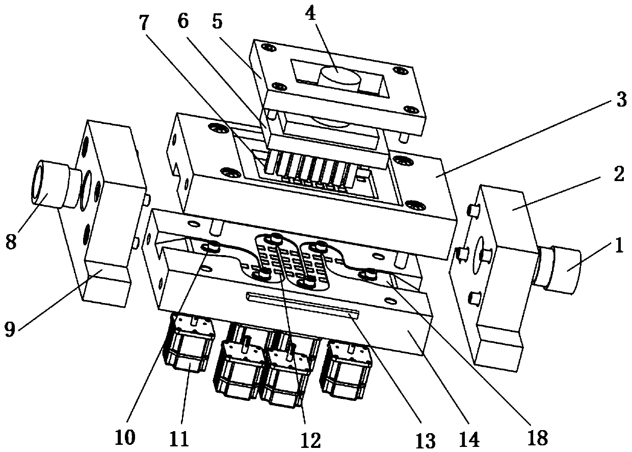
[0030] The present invention proposes an electrolytic machining tool and method in which the rotation of the barbed cam promotes the periodic fluctuation of the flow field, such as figure 1 As shown, the anode workpiece 14 and the cathode block 7 are placed in the clamp body, the electrolyte flows in from the liquid inlet pipe 8, passes through the continuously narrowed inner flow channel, flows through the barbed cam 10 and the processing area 12, and flows from the liquid outlet pipe 1 flow out.

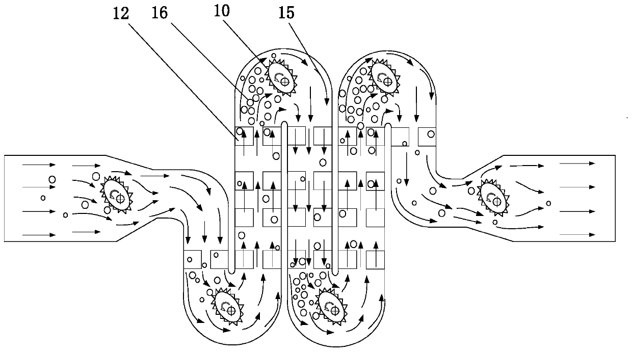
[0031] Such as image 3 As shown, at the constricted section of the flow channel and the corner of the flow channel, the barbed cam 10 mechanism rotates at high speed under the control of the drive motor 11, and the spikes on the surface of the cam can pierce continuous air bubbles to prevent them from affecting the subsequent processing area.

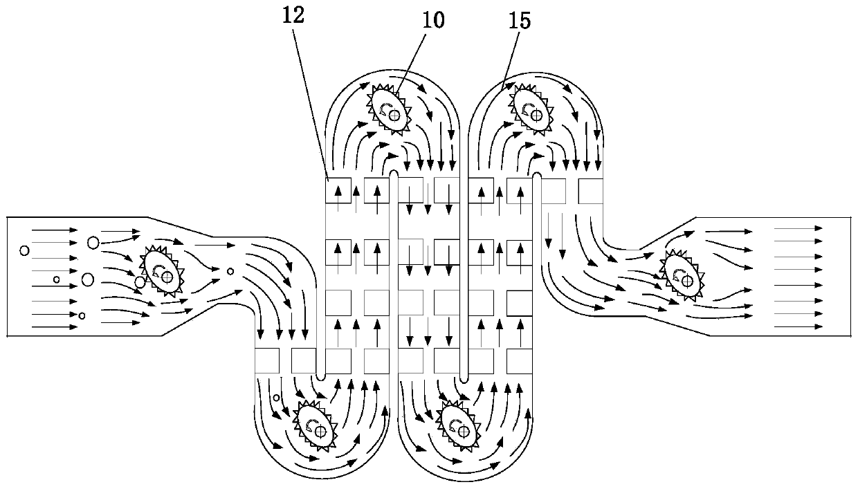
[0032] Such as figure 2 , F...


PUM


Abstract

The invention discloses an electrolytic machining tool enabling flow field period fluctuation and a method, and belongs to the technical field of electrolytic machining. Due to the arrangement of a barbed cam mechanism in a device flow channel, the flow and the flow rate of an electrolyte in a machining flow channel fluctuate periodically, the electrolyte is promoted to flush the surface of a workpiece in a wave manner, a machining product is taken away quickly, and the surface quality of electrolytic machining is improved. In addition, spikes distributed throughout the surface of a barbed camcan pierce bubbles generated in the electrolytic action of the workpiece, the influence of the bubbles on later workpiece electrolytic machining is reduced, and the stability and the uniformity of electrolytic machining are improved. The electrolytic machining tool enabling flow field period fluctuation and the method have important significance in improving the electrolytic machining surface quality, machining stability and uniformity.

Description

technical field [0001] The invention relates to an electrolytic machining tool and method with periodic fluctuations in a flow field, belonging to the field of electrolytic machining. Background technique [0002] With the development of society and the advancement of science and technology, more and more special metal materials will be used in modern aerospace and other fields. For these special materials such as superalloys and titanium alloys, due to their poor thermal conductivity and high strength and hardness, traditional The traditional mechanical processing is no longer applicable, and the electrolytic machining stands out because of its unique non-contact processing characteristics. [0003] There is no cutting force in the electrolytic machining process, no loss to the tool, and no requirements on the hardness and strength of the material, so it is very suitable for the processing of some difficult-to-machine materials in aerospace and other fields. In electrolyti...

Claims


Application Information

Patent Timeline
Patent Type & Authority Applications(China)
IPC IPC(8): B23H3/00B23H3/10
CPCB23H3/00B23H3/10
Inventor 刘洋曲宁松谢洲冯瑞
Owner NANJING UNIV OF AERONAUTICS & ASTRONAUTICS
Learn More