Textile yarn roll continuous feeding device

A technology of yarn reeling and rewinding, which is applied in the direction of thin material handling, transportation and packaging, and delivery of filamentous materials, etc. The effect of high degree of automation and reasonable structure design

Active Publication Date: 2020-02-18
TONGXIANG YUESHUN WRAP KNITTING
View PDF9 Cites 2 Cited by
  • Summary
  • Abstract
  • Description
  • Claims
  • Application Information

AI Technical Summary

Problems solved by technology

When the existing textile yarn rolls are transferred to the required unwinding station to unwind and transmit the yarn, it is necessary to manually place the textile yarn rolls to the unwinding station one by one to realize the unwinding of the yarn rolls. The strength is high, and it is difficult to place the textile yarn rolls to the desired position quickly and steadily one by one, and in the process of modern large-scale fabric production and processing, it is difficult to place the textile yarn rolls manually to meet the requirements of large quantities of yarn. Due to the needs of production, the existing textile yarn roll transfer and feeding mechanism has a complex structure and troublesome operation, and it is difficult to smoothly transfer the textile yarn roll to the desired position, and the existing transfer mechanism is difficult in the process of transferring the textile yarn roll. The stable and accurate supporting and fixing of the yarn rolls will cause the textile yarn rolls to fall off easily during the transfer process, affecting the normal and stable continuous transfer and loading of the textile yarn rolls, which cannot meet the needs of production and use.

Method used


Image

  • Textile yarn roll continuous feeding device
  • Textile yarn roll continuous feeding device
  • Textile yarn roll continuous feeding device

Examples


Embodiment Construction

[0019] In order to further describe the present invention, a specific implementation of a textile yarn roll continuous feeding device will be further described below in conjunction with the accompanying drawings. The following examples are explanations of the present invention and the present invention is not limited to the following examples.

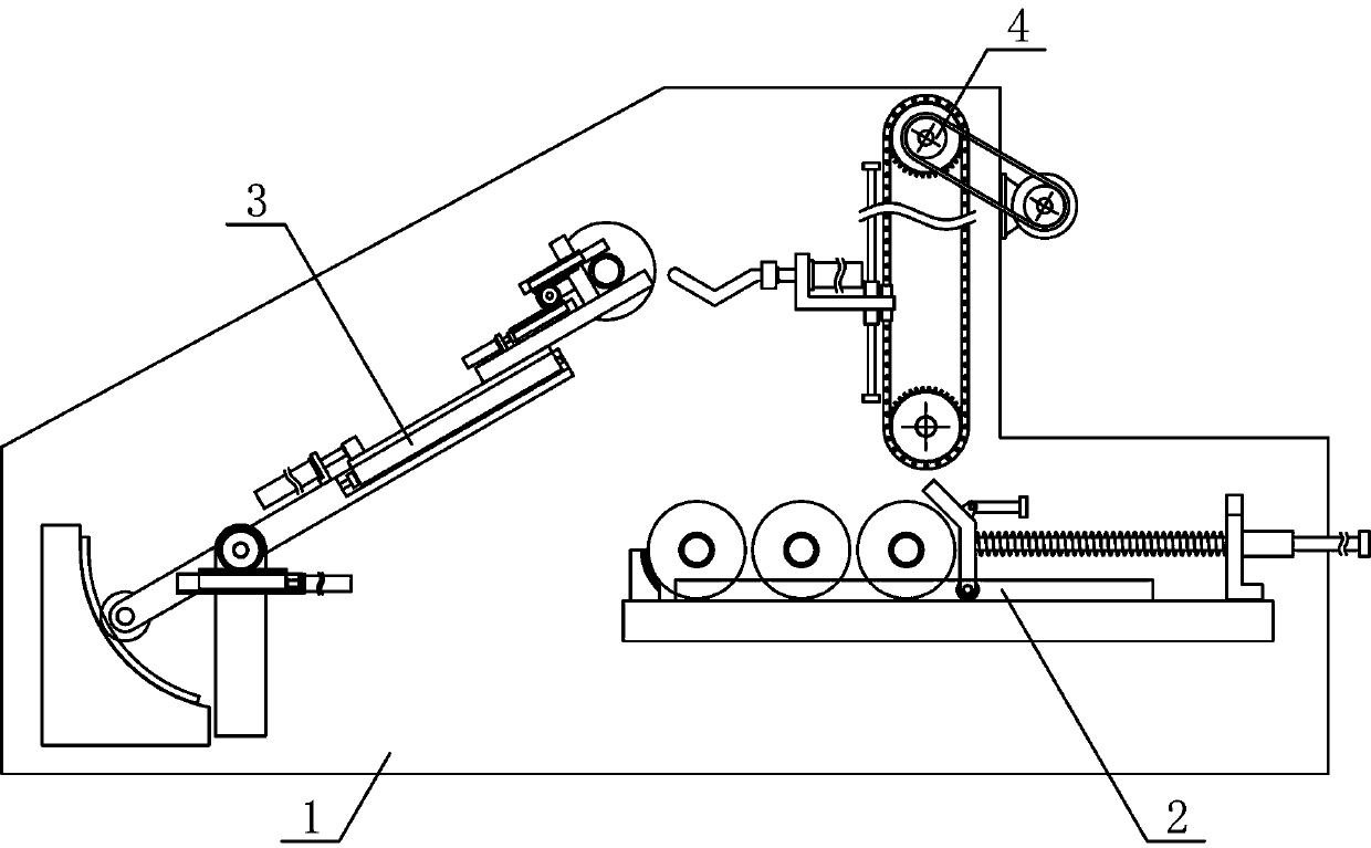
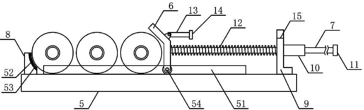
[0020] Such as figure 1 As shown, a continuous feeding device for textile yarn rolls in the present invention includes a material transfer bracket 1, an unwinding mechanism 2, a rolling mechanism 3 and a winding mechanism 4, and the winding mechanism 4 and the unwinding mechanism 2 are sequentially arranged from top to bottom Fixedly arranged on the material transfer bracket 1, the roll-moving mechanism 3 is arranged on the material transfer bracket 1 on one side of the unwinding mechanism 2, such as figure 2 As shown, the unwinding mechanism 2 of the present invention includes an unwinding support plate 5, a rolling translation plate...


PUM


Abstract

The invention discloses a textile yarn roll continuous feeding device, and belongs to the field of textile processing mechanical equipment. A roll pushing and translation plate of the device is placedon the upper side of an unwinding bearing plate, the two ends of one side of the roll pushing and translation plate are fixedly connected with ends of roll pushing guide rods on the two sides of a guide rod support, a reciprocating guide plate sliding groove is formed in the upper side of a roll moving rotary plate, a roll pushing guide plate is arranged in the reciprocating guide plate sliding groove, and the output end of a roll pushing cylinder is fixedly connected with one side of the roll pushing guide plate. A roll clamping mechanism is fixedly arranged on the upper side of the roll pushing guide plate, two sides of a roll feeding chain are in wound connection with an upper rotating chain wheel and a lower rotating chain wheel respectively, a lifting support is vertically and slidably arranged on a lifting guide rod, the upper and lower ends of one side of the roll feeding chain are fixedly connected with the upper and lower sides of the lifting support respectively, and a rollfeeding baring plate is horizontally and fixedly disposed on one side of a horizontal pushing connecting plate. The device is reasonable in structural design, textile yarn rolls can be quickly and efficiently transferred and conveyed stably and smoothly one by one, the automation degree of feeding is high, and production and use requirements are met.

Description

technical field [0001] The invention belongs to the field of textile processing machinery and equipment, in particular to a continuous feeding device for textile yarn rolls, which is mainly used for yarn roll transfer and textile processing. Background technique [0002] Yarn is the basic raw material for fabric weaving. Knitted fabrics can be classified into weft-knitted fabrics and warp-knitted fabrics according to the weaving method. Commonly used weft-knitted fabrics are mainly made of low-elastic polyester yarn or special-shaped polyester yarn, nylon yarn , cotton yarn, wool yarn, etc. are used as raw materials, and are woven on various weft knitting machines using plain stitches, variable flat stitches, rib plain stitches, double rib plain stitches, jacquard stitches, and terry stitches. Yarn is the basic raw material for fabric weaving. In the process of yarn production and processing, it is necessary to wind the incoming cotton yarn into a textile yarn roll with a ce...

Claims


Application Information

Patent Timeline
Patent Type & Authority Applications(China)
IPC IPC(8): B65H67/06B65G47/52B65G47/82
CPCB65G47/52B65G47/82B65H67/06
Inventor 倪月松
Owner TONGXIANG YUESHUN WRAP KNITTING
Why Eureka
Try Eureka