
Multifunctional cleaning device

A cleaning equipment and multi-functional technology, applied in cleaning equipment, cleaning machinery, carpet cleaning, etc., can solve the problems of reducing cleaning efficiency, time-consuming, low efficiency, etc., to increase cleaning efficiency, increase cleaning effect, heat conduction good performance

Active Publication Date: 2020-02-21
深圳市思创力石材护理有限公司
View PDF10 Cites 1 Cited by
  • Summary
  • Abstract
  • Description
  • Claims
  • Application Information

AI Technical Summary

Problems solved by technology

[0003] 1. When cleaning, generally use a vacuum cleaner to clean the ground first, then use a mop or rag to wipe the floor. It is necessary to change tools back and forth, which is troublesome, time-consuming, and reduces cleaning efficiency.
[0004] 2. If you encounter some garbage that is closely adhered to the ground, such as chewing gum or tape, you need to use a shovel to separate the garbage from the ground first, and then use a vacuum cleaner to clean it. It is laborious to shovel back and forth with a shovel manually, and switch back and forth Tools lead to inefficiencies and increased use of manpower

Method used


Image

  • Multifunctional cleaning device
  • Multifunctional cleaning device
  • Multifunctional cleaning device

Examples


Embodiment 1

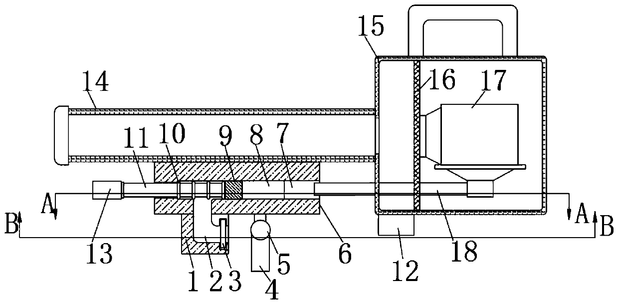
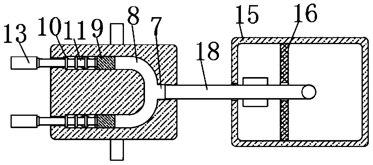
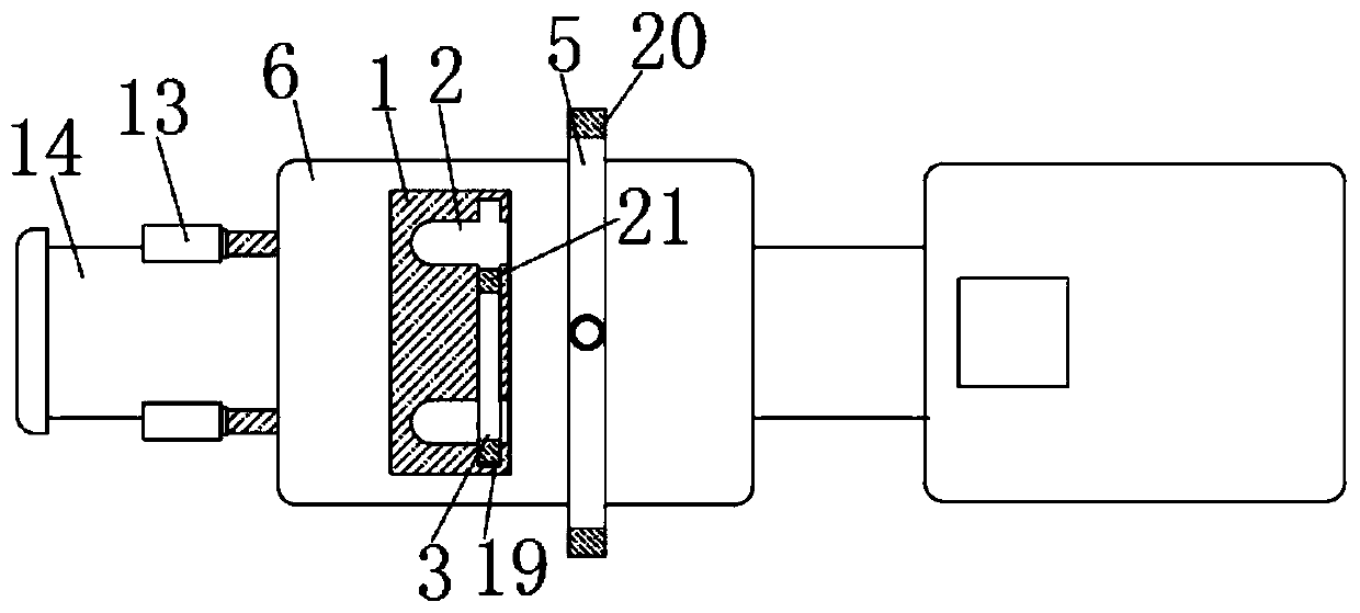
[0022] refer to Figure 1-5 , a multi-functional cleaning device, including a housing 15, a dust suction pipe 14 is installed on one side of the housing 15, and one end of the dust suction pipe 14 extends into the housing 15, and an induced draft fan 17 is installed in the housing 15. The air inlet of blower fan 17 is facing one end of suction pipe 14, and the air outlet of induced draft fan 17 is connected with air outlet pipe 18, and dust-proof net 16 is installed in housing 15, prevents dust or rubbish from entering in induced draft fan 17, housing The lower end of the body 15 is equipped with a dust collection box 12, and the lower end of the dust suction pipe 14 is fixedly connected with a connecting plate 6, and the connecting plate 6 is symmetrically provided with two branch air ducts 8, and the two branch air ducts 8 are connected together to form a main air duct 7. The end of the air outlet pipe 18 away from the air outlet of the induced draft fan 17 extends into the ...

Embodiment 2

[0025] refer to Image 6 The difference between this embodiment and Embodiment 1 is that a layer of friction tiles 22 is provided on the outside of the connecting rod 11, and the material of the connecting rod 11 is metal.

[0026] In this embodiment, when in use, when the two cleaning tools 13 are reciprocating, they will drive the friction tiles 22 on them to rub against the inner wall of the corresponding branch air duct 8, and the friction will generate a large amount of heat. Passed on the cleaning tool 13 by the connecting rod 11, the cleaning tool 13 is also made of metal, and the thermal conductivity of the metal material is good, and the rising of the temperature of the cleaning tool 13 will make it easier to shovel garbage such as chewing gum or adhesive tape.


PUM


Abstract

The invention discloses a multifunctional cleaning device which comprises a shell; a dust suction pipe is installed on one side of the shell; one end of the dust suction pipe extends into the shell; an induced draft fan is installed in the shell; an air suction hole of the induced draft fan directly faces one end of the dust suction pipe; an air outlet of the induced draft fan is connected with anair outlet pipe; the lower end of the shell is provided with a dust collection box; the lower end of the dust suction pipe is fixedly connected with a connecting plate; two branch air channels are symmetrically arranged in the connecting plate; the two branch air channels jointly communicate with a main air channel; the end, away from the air outlet of the induced draft fan, of the air outlet pipe extends into the main air channel; and a moving mechanism which moves leftwards and rightwards is arranged in each of the two branch air channels. The cleaning device integrates shoveling, suction and wiping, and tools do not need to be replaced for multiple times in the cleaning process, so that the cleaning efficiency is greatly improved.

Description

technical field [0001] The invention relates to the field of cleaning equipment, in particular to a multifunctional cleaning equipment. Background technique [0002] Cleaning refers to cleaning the floors, walls, ceilings, balconies, rooms, toilets and other parts of the living room by professional cleaning personnel using cleaning equipment, tools and agents, and performing targeted cleaning on doors, windows, glass, stoves, furniture, furniture, etc. It is an activity to achieve the purpose of environmental cleaning, sterilization and anticorrosion, and article maintenance. When cleaning a small area, small cleaning tools are used for cleaning. The current cleaning tools have the following problems. [0003] 1. When cleaning, generally use a vacuum cleaner to vacuum first, and then use a mop or rag to wipe the floor. It is necessary to change tools back and forth, which is troublesome, time-consuming, and reduces cleaning efficiency. [0004] 2. If you encounter some garb...

Claims


Application Information

Patent Timeline
Patent Type & Authority Applications(China)
IPC IPC(8): A47L11/00A47L11/40
CPCA47L11/00A47L11/40A47L11/4036A47L11/4069A47L11/4094
Inventor 邢明明
Owner 深圳市思创力石材护理有限公司
Learn More