Gynecologic vulva cleaning device adopting multi-tube structure

A technology of cleaning device and tube structure, applied in the direction of enema/irrigator, resistance to vector-borne diseases, syringes, etc., can solve the problems of cleaning head pollution, low sanitation, inconvenience, etc., and achieve the effect of reasonable structural design

Active Publication Date: 2020-02-21
郭艳华
View PDF6 Cites 1 Cited by
  • Summary
  • Abstract
  • Description
  • Claims
  • Application Information

AI Technical Summary

Problems solved by technology

In the daily rehabilitation nursing process of gynecological diseases, the vulva is often cleaned to prevent the growth of bacteria. In the cleaning process, the medical staff usually wash the water directly by hand, which is not only not hygienic, but also very inconvenient
In the Chinese invention patent with the notification number CN109876227A, a guiding cleaning device for gynecological care is disclosed. The distance between the patient's legs can be adjusted through an adjustable support structure, which is convenient for cleaning. In addition, there are three sets of storage The liquid cylinders are convenient for storing different liquid medicines, but since the three sets of liquid storage cylinders are connected with their own cleaning tubes, when medical staff or patients use one of the cleaning tubes, the other two cleaning tubes are in an idle state, which is extremely dangerous. The cleaning head may be contaminated due to contact with the floor

Method used


Image

  • Gynecologic vulva cleaning device adopting multi-tube structure
  • Gynecologic vulva cleaning device adopting multi-tube structure
  • Gynecologic vulva cleaning device adopting multi-tube structure

Examples


Embodiment Construction

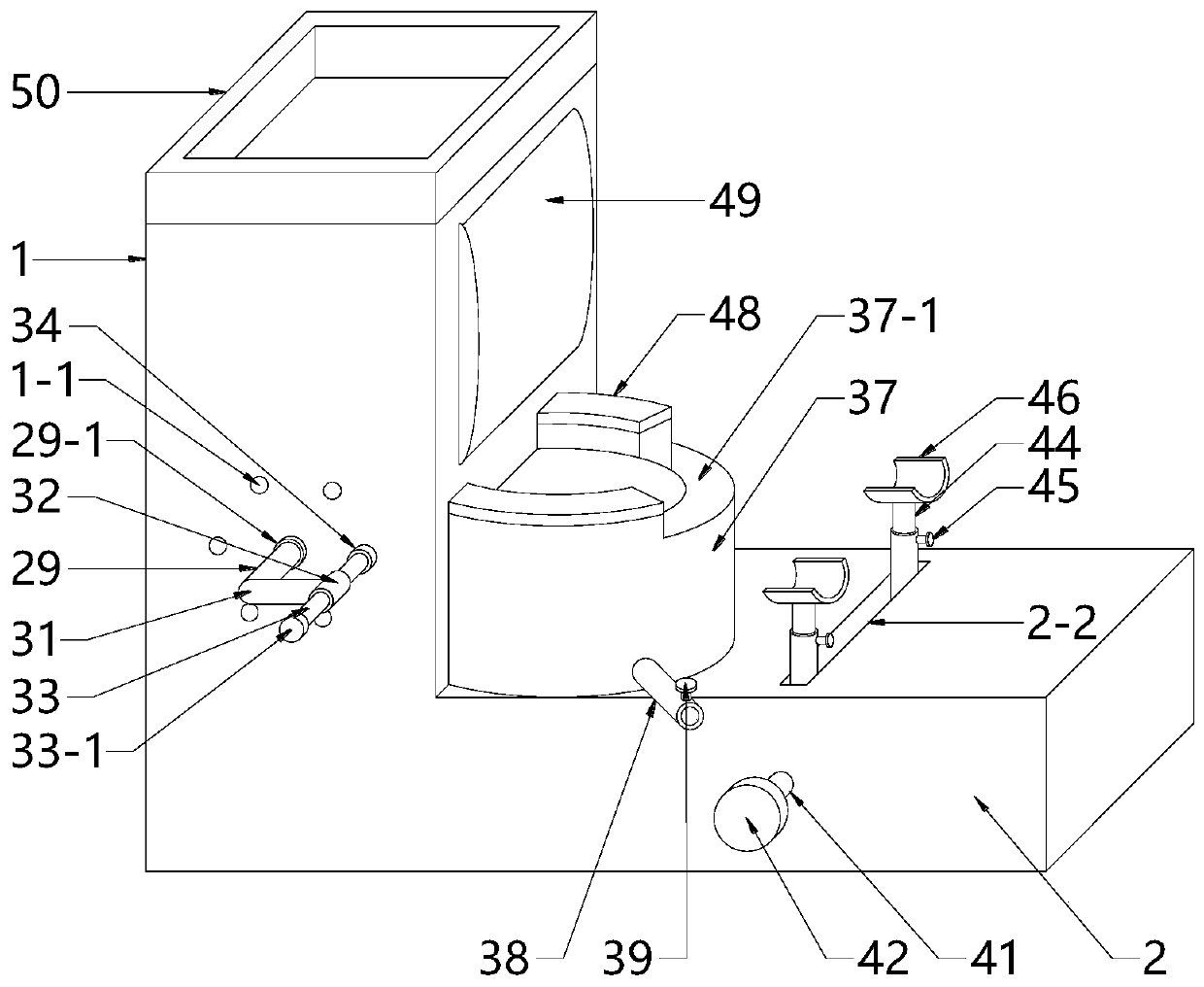
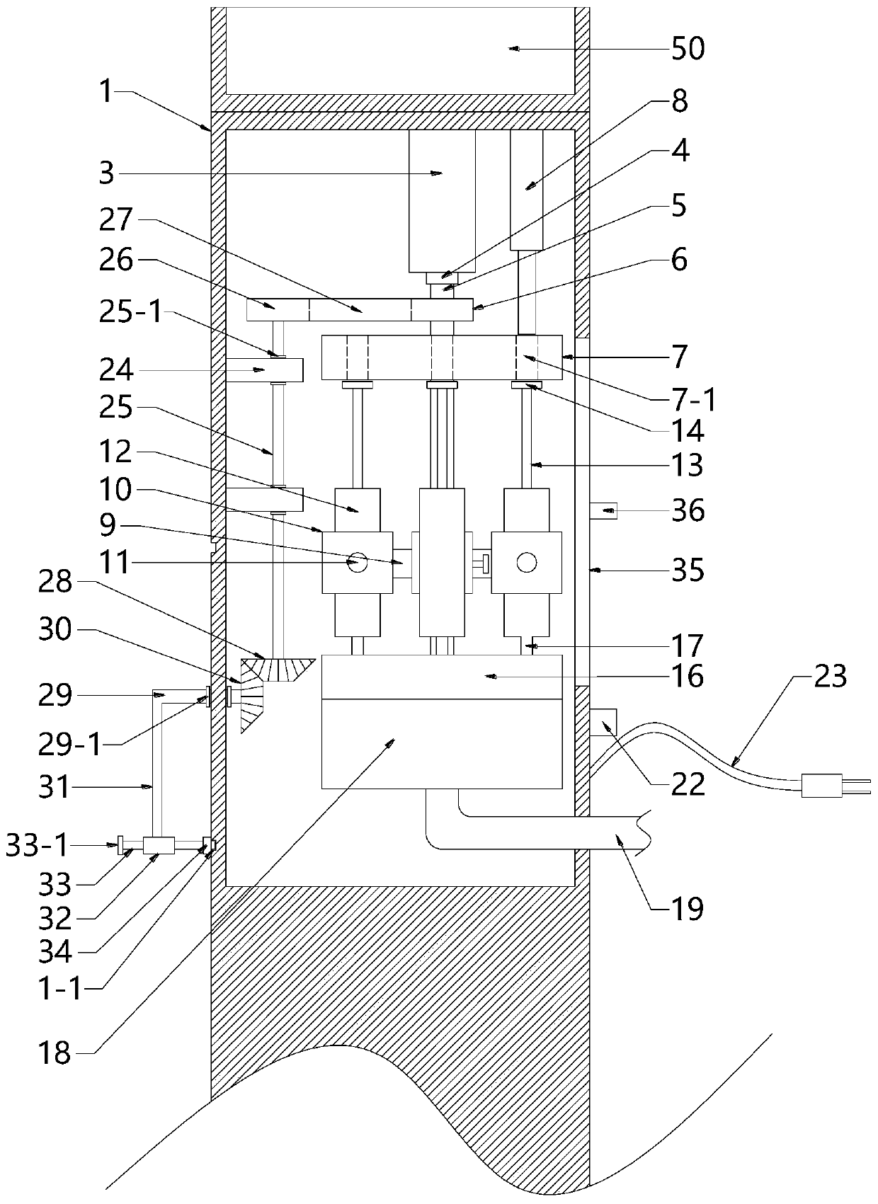
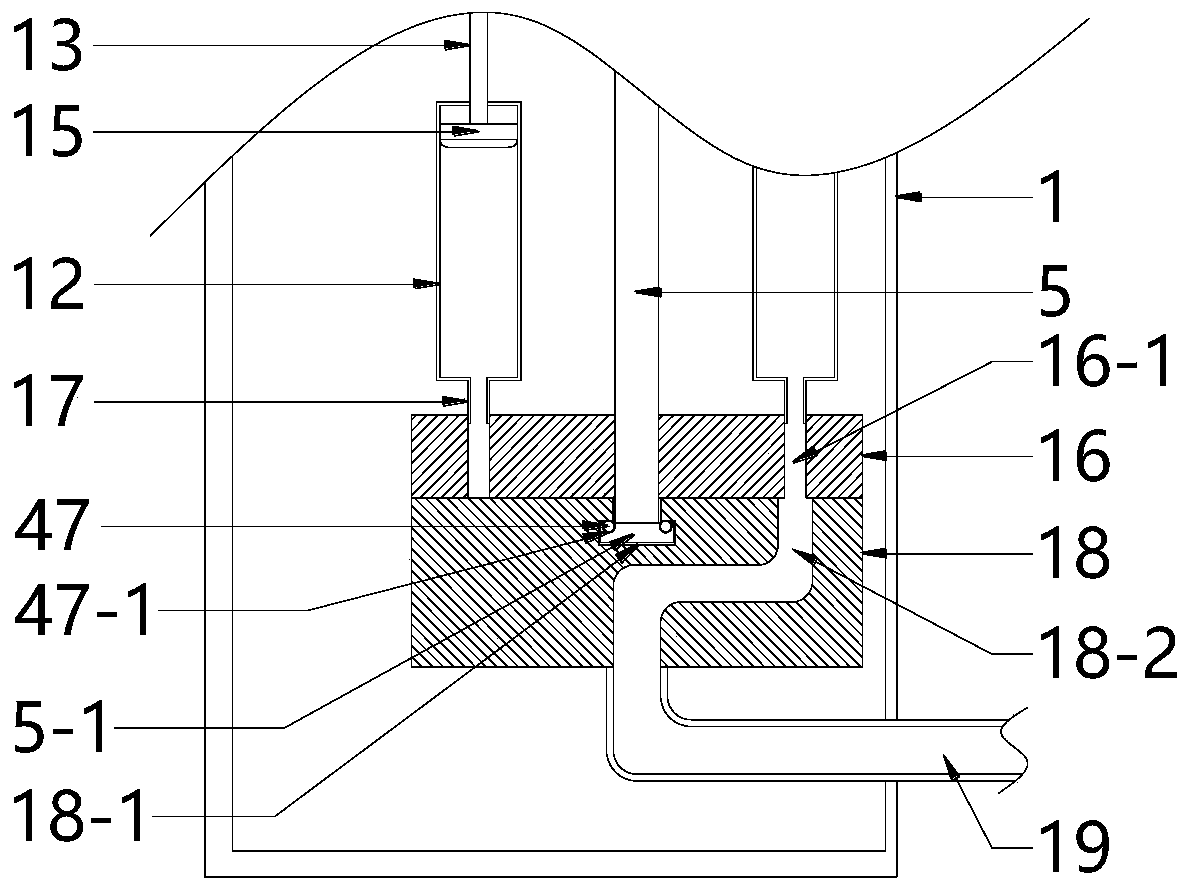
[0016] Attached below Figure 1~6 The present invention is described in detail below.

[0017] Such as Figure 1~6 shown, and attached figure 1For the azimuth reference, the present invention includes a box body 1, a base 2 and a storage bucket 37, the box body 1 is affixed to the upper left of the base 2, a connection seat 3 is affixed to the inner top of the box body 1, and the lower end of the connection seat 3 passes through the first The bearing 4 is connected with a central shaft 5, the top of the central shaft 5 is fixedly connected with a first transmission chainring 6, and the upper part of the central shaft 5 is fixedly connected with an upper turntable 7, and the upper turntable 7 is provided with six first through holes 7-1, each The included angles between two adjacent first through holes 7-1 and the center of the upper turntable 7 are both 60°, and an electric telescopic rod 8 is fixedly connected to the right side of the connecting seat 3 on the inner top surf...


PUM


Abstract

The invention relates to the technical field of nursing devices, in particular to a gynecologic vulva cleaning device adopting a multi-tube structure. The gynecologic vulva cleaning device comprises abox, a base and a storage barrel, wherein the box is fixedly connected to the upper left side of the base, a central shaft is arranged in the box, an upper rotating disc is fixedly connected to the upper part of the central shaft, six first through holes are uniformly formed in the upper rotating disc, six connecting rods are fixedly connected to the middle of the central shaft, the tail ends ofthe connecting rods are fixedly connected with U-shaped frames, medicine barrels are connected in the U-shaped frames in a clamping manner, a lower rotating disc is fixedly connected to the lower partof the central shaft, six second through holes are uniformly formed in the lower rotating disc, a rotating shaft is connected to the front side wall of the box in an insertion manner, six insertion holes are annularly formed in the front end surface of the box, the six insertion holes take the rotating shaft as the center, the included angle formed by every two adjacent insertion holes and the rotating shaft is 60 degrees, the storage barrel is fixedly connected to the upper end surface of the base, and a notch is formed in the right side of the upper end surface of the storage barrel. The gynecologic vulva cleaning device is reasonable in structural design, insertion rods are inserted into different insertion holes by rotating the rotating shaft, so that a spray nozzle sprays different medicine liquids, use of multiple cleaning tubes is not needed, and the gynecologic vulva cleaning device is very convenient.

Description

technical field [0001] The invention relates to the technical field of nursing appliances, in particular to a gynecological vulva cleaning device with a multi-tube structure. Background technique [0002] Gynecology is a diagnosis and treatment subject in medical institutions. Gynecology is a branch of obstetrics and gynecology. It is a professional department that diagnoses and treats female gynecological diseases. It is divided into western medicine gynecology and traditional Chinese medicine gynecology. Gynecological diseases include: diseases of the female reproductive system are gynecological diseases, including vulvar diseases, vaginal diseases, uterine diseases, fallopian tube diseases, ovarian diseases, etc. In the daily rehabilitation nursing process of gynecological diseases, the vulva is often cleaned to prevent the growth of bacteria. In the cleaning process, the medical staff usually wash the water directly by hand, which is not only not hygienic, but also very ...

Claims


Application Information

Patent Timeline
IPC IPC(8): A61M3/02
CPCA61M3/0225A61M3/0237Y02A50/30
Inventor 于宏伟
Owner 郭艳华
Why Eureka
Try Eureka