Shell embossing device for electronic product production

An electronic product and embossing technology, which is applied in the fields of decorative arts, cleaning methods and utensils, cleaning methods using tools, etc., can solve the problems of low production efficiency and inability to produce multiple embossed shells at the same time, so as to improve efficiency and improve Processing suitability, effect of improving embossing speed

Inactive Publication Date: 2020-02-21
南京市旗心电子科技有限公司
View PDF9 Cites 5 Cited by
  • Summary
  • Abstract
  • Description
  • Claims
  • Application Information

AI Technical Summary

Problems solved by technology

[0006] Aiming at the deficiencies of the prior art, the present invention provides a shell embossing device for the production of electronic prod

Method used


Image

  • Shell embossing device for electronic product production
  • Shell embossing device for electronic product production
  • Shell embossing device for electronic product production

Examples


Example Embodiment

[0031] Example 1

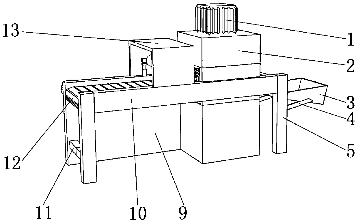
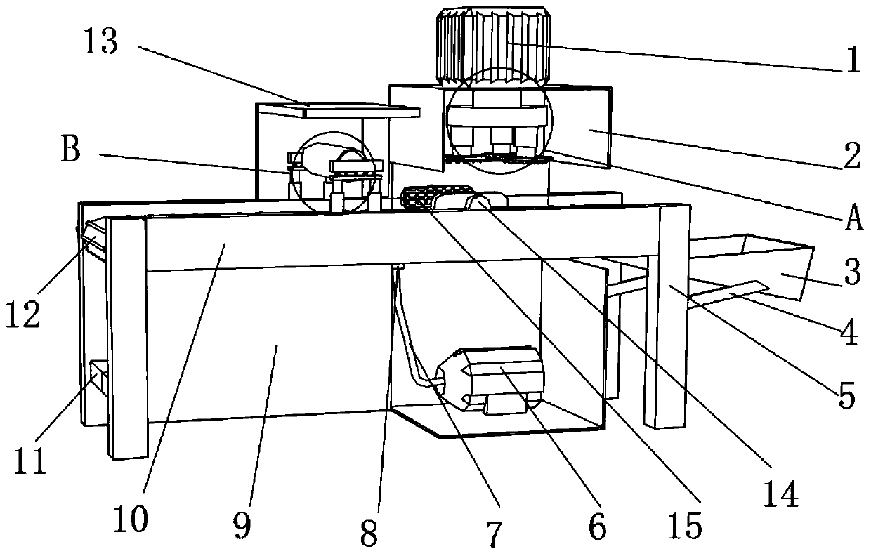
[0032] Reference Figure 1-5 , A shell embossing device for the production of electronic products, comprising a bearing plate 9, a supporting leg 5, a baffle 10, a first box body 2 and a second box body 13, and the bearing plate 9 and the supporting leg 5 are fixedly connected with each other. The rod 11, the load-bearing plate 9, the supporting leg 5 and the baffle 10 are fixedly installed to form a mounting frame. The first box body 2 and the second box body 13 are fixedly installed on the mounting frame, and the top of the outer wall of the first box body 2 is fixedly connected with Stepping motor 1, and the output end of the stepping motor 1 is fixedly connected with a printing assembly. The printing assembly includes a rotating shaft 21. The top end of the rotating shaft 21 and the bottom end of the output shaft of the stepping motor 1 are connected by a coupling. The bottom of the rotating shaft 21 is open There is a groove, and a plurality of pressure r...

Example Embodiment

[0035] Example 2

[0036] Reference Image 6 , A shell embossing device for the production of electronic products. Compared with the embodiment 1, the main difference of this embodiment is that in this embodiment, an observation port 23 is opened on one side of the first box body 2 so that the first box body 2 can be observed. The internal conditions not only improve the quality of embossing, but also avoid safety accidents.

[0037] The working principle of this embodiment: When it is necessary to check the embossing condition of the product shell in the first box 2, it can be observed through the observation port 23.

[0038] The electrical components appearing in this article are all connected to the external main controller and 220V mains power, and the main controller can be a computer and other conventional known equipment that controls.


PUM


Abstract

The invention relates to the technical field of electronic product processing, and discloses a shell embossing device for electronic product production. The shell embossing device comprises a bearingplate, supporting legs, a baffle, a first box body and a second box body, wherein the bearing plate, the supporting legs and the baffle are fixedly mounted each another to form a mounting frame, the first box body and the second box body are fixedly mounted on the mounting frame, the top end of the outer wall of the first box body is fixedly connected with a stepping motor, the output end of the stepping motor is fixedly connected with a printing assembly, the printing assembly comprises a rotating shaft, and the top end of the rotating shaft is connected with the bottom end of the output shaft of the stepping motor through a coupler. According to the shell embossing device, a product shell is cleaned by a dust removing rubber roller before embossing, and springs enable the dust removing rubber roller to automatically and finely adjust the position, so that the dust removing rubber roller makes contact with the upper surface of raw materials more closely, and the cleaning effect of thedevice is improved; and multiple embossing heads are arranged, and the multiple embossing heads can work at the same time, so that produced shell flower types are increased, and the machining applicability is improved.

Description

Technical field [0001] The invention relates to the technical field of electronic product processing, in particular to a shell embossing device for electronic product production. Background technique [0002] With the development of my country's economy and society, electronic products have gradually become an indispensable part of people's lives. Electronic products have developed most rapidly in the 20th century. In order to adapt to the rapid development of electronic products, the production machinery of electronic products has also followed closely and developed rapidly. Embossing equipment for electronic product shells is an important production device for electronic products and has been widely used. [0003] After searching, the patent with the authorized publication number CN208180243U discloses a shell embossing device for the production of electronic products, including a worktable, a stepping motor, and a clamping cylinder. The support is provided with the worktable, a...

Claims


Application Information

Patent Timeline
IPC IPC(8): B08B1/02B44B5/00B44B5/02
CPCB08B1/006B08B1/02B44B5/0047B44B5/0057B44B5/0061B44B5/02B44B5/022B44B5/024B44B5/026
Inventor 陈志勇龙恩朱和梁
Owner 南京市旗心电子科技有限公司
Why Eureka
Try Eureka