Snap ring machining process for asynchronous motor

An asynchronous motor and processing technology, which is applied in the field of processing technology of a snap ring for asynchronous motors, can solve the problems affecting the use of components, changes in the size and shape and position tolerances of the half-end parts, and inconsistent dimensional changes, so as to save costs, ensure accuracy, Guaranteed success rate

Inactive Publication Date: 2020-02-21
HARBIN ELECTRIC POWER EQUIP
View PDF6 Cites 2 Cited by
  • Summary
  • Abstract
  • Description
  • Claims
  • Application Information

AI Technical Summary

Problems solved by technology

Due to the larger diameter and thinner wall thickness of the snap ring for asynchronous motors, the practice of this process method has the following obvious shortcomings: After the full circle finishing is completed, the measured size meets the requirements of the drawing. When beveling, it was found that the size of the opening of the half-ring became larger, and the size of the two half-clips changed inconsistently, resulting in a "dislocation" phenomenon when the two half-rings were centered. The internal stress is kept balanced, and the measured dimensions meet the requirements of the drawing. After the snap ring is cut into half by the full circle line, due to the change of the internal stress, the balance is no longer maintained, and the internal stress is released again, resulting in the size and shape tolerance of the half end after finishing. Changes, resulting in the final size not meeting the requirements of the drawing, affecting the use of the part

Method used


Image

  • Snap ring machining process for asynchronous motor
  • Snap ring machining process for asynchronous motor

Examples


Embodiment Construction

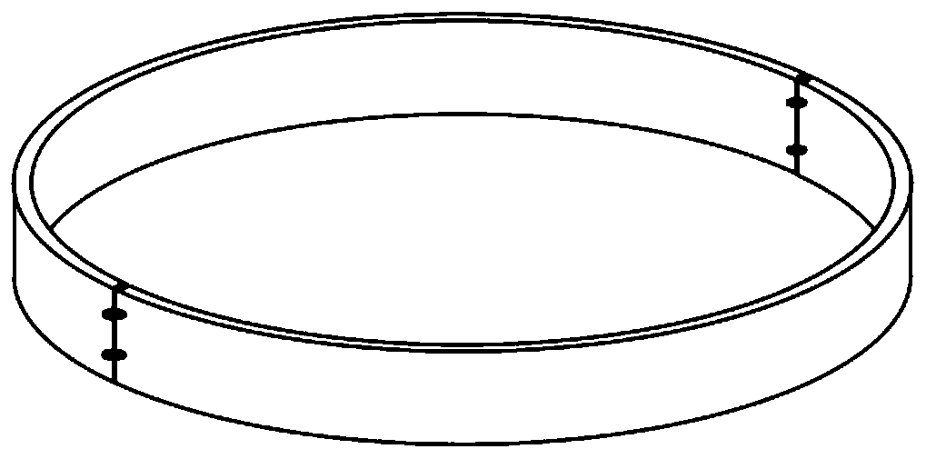
[0020] a) After alignment, the whole piece of snap ring for asynchronous motor is cut into two halves by wire cutting;

[0021] b) Plan the two halves of the joint surface of the snap ring for asynchronous motor flat, with a roughness of at least Ra3.2;

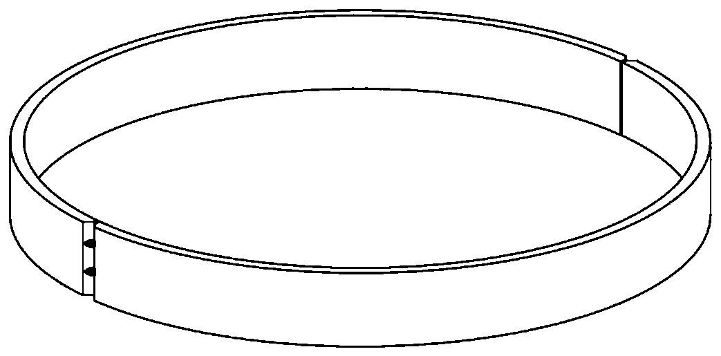
[0022] c) Align the two halves of the snap ring for the asynchronous motor after b) and use the chuck jaws to assist in clamping the workpiece. The gap between the two halves should not be greater than 0.02mm. Spot weld the two halves of the asynchronous motor together with the snap ring. One point of spot welding on both ends of the snap ring for asynchronous motors, and two spot welding points on the joints of the inner circle and outer circle of the snap ring for asynchronous motors;

[0023] d) The snap rings for asynchronous motors that are spot welded together by rough turning, process the inner circle, outer circle and upper end face of the snap rings for asynchronous motors, leave a machining allowance of 4 mm for the...


PUM


Abstract

The invention relates to a snap ring machining process for an asynchronous motor. Each semi-ring is made from stainless steel, the inner hole diameter is Phi341.6D8(+0.21 / +0.299), the wall thickness is 7mm, the width dimension is 40, the semi-ring and a snap ring groove are subjected to matching machining, and the gap is 0.03-0.09mm. When a method of halving after finish machining rounding is completed is adopted, the dimensions of the halved semi-rings are changed due to stress change, so that the halved semi-rings cannot meet the use requirements; in the machining method, rough machining iscarried out at first to obtain dimension allowances, joint surfaces are milled after wire cutting halving, the two semi-rings are combined through spot welding, rough turning is carried out to obtaindimensions, the joint surfaces are milled, finish machining is carried out after the spot welding for the joint surfaces, and grinding machining is carried out to obtain the grinding allowances of thethickness dimensions during the finish machining. The method is capable of ensuring that the dimensions after final machining cannot be changed due to the stress change, so that the accuracy of dimension tolerance, and form and location tolerance, and the assembly accuracy in the later period are ensured.

Description

Technical field: [0001] The invention relates to a processing technology of a snap ring for an asynchronous motor. Background technique: [0002] With the development of motor technology, more research has been done on the solid rotor of the motor. The solid rotor asynchronous motor has the advantages of simple structure, "soft" mechanical characteristics, and low manufacturing cost. After the core groove of the solid rotor is processed, the copper bars are assembled, and multiple positions in the middle of the copper bars need to be fixed with snap rings. The snap rings are a pair of half-ring centered welding structures. Since the rotor is a rotating part with a high speed, the processing requirements for the snap ring are relatively high, and the assembly accuracy of the snap ring and the iron core slot is also very high. [0003] The existing processing method for paired half-rings is to finish the inner circle, outer circle and end face of the snap ring for asynchronou...

Claims


Application Information

Patent Timeline
Patent Type & Authority Applications(China)
IPC IPC(8): B23P15/00
CPCB23P15/00
Inventor 于志佳黄秀波张涛杨立峰王志威唐浩宇孙学森高明缙朱新
Owner HARBIN ELECTRIC POWER EQUIP
Why Eureka
Try Eureka