Displacement detection wheel, robot chassis and movable robot

A mobile robot and displacement detection technology, which is applied in the direction of motor vehicles, instruments, manipulators, etc., can solve the problems of driving wheel slipping and inaccurate moving distance of the robot, and achieve the effects of avoiding slipping, guaranteeing wide applicability, and small changes

Pending Publication Date: 2020-02-21
湖南合控智能技术有限公司
View PDF2 Cites 4 Cited by
  • Summary
  • Abstract
  • Description
  • Claims
  • Application Information

AI Technical Summary

Problems solved by technology

However, since the encoder is directly arranged on the driving wheel or the driving motor, once obstacles block or the ground is wet and slippery, the driving wheel will slip, resulting in inaccurate moving distance of the robot converted by the encoder

Method used


Image

  • Displacement detection wheel, robot chassis and movable robot
  • Displacement detection wheel, robot chassis and movable robot
  • Displacement detection wheel, robot chassis and movable robot

Examples


Embodiment Construction

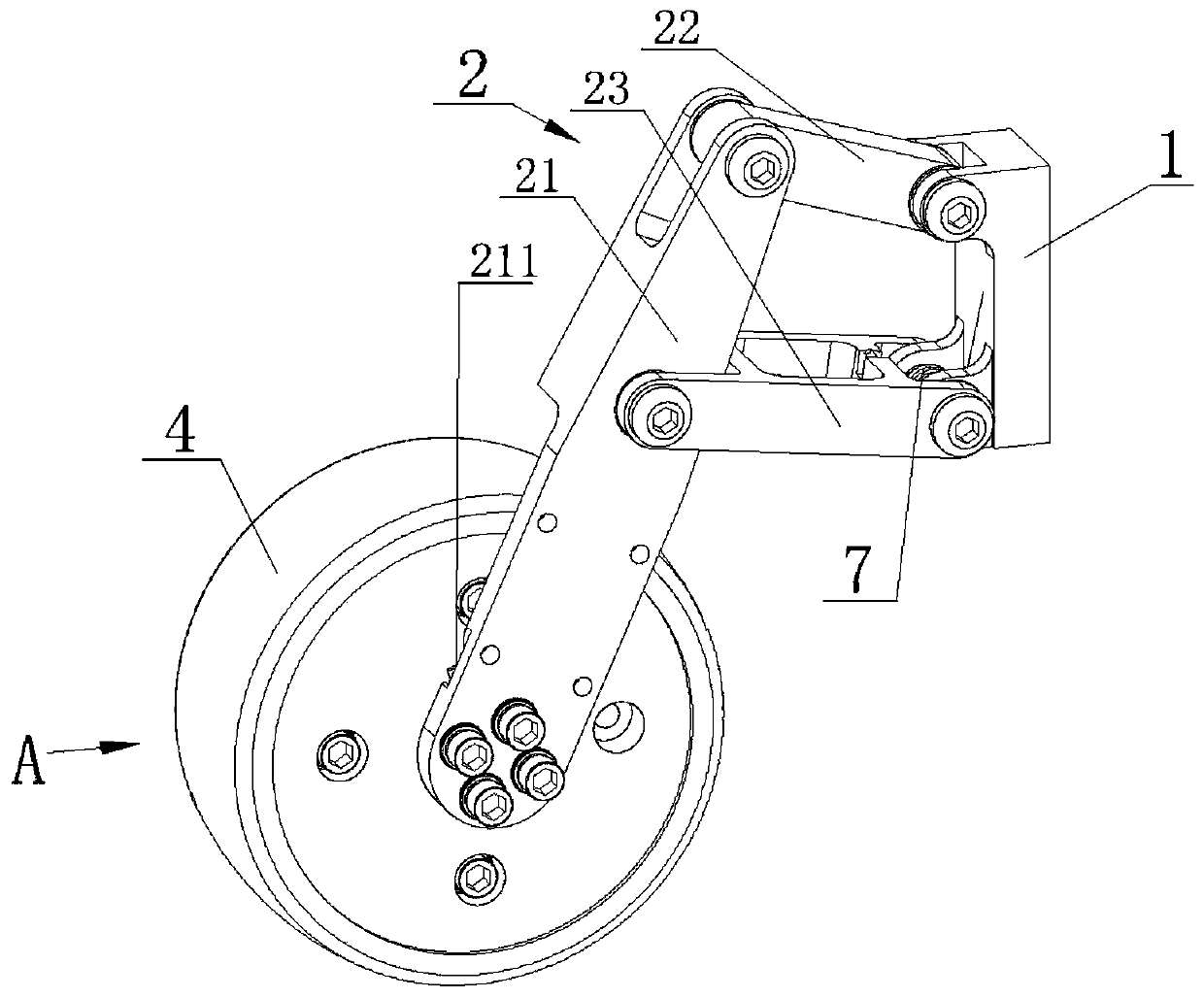
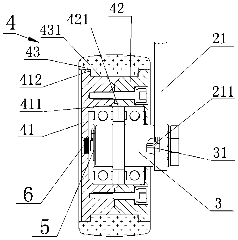
[0028] from figure 1 and figure 2 It can be seen that the displacement detection wheel of the present invention includes a fixed bracket 1, a Hawken linear mechanism 2, an axle 3, a displacement wheel 4, a magnetoelectric encoder 5, a strong magnet 6 and a torsion spring 7,

[0029] The fixed bracket 1 is detachably installed on the chassis of the mobile robot through threaded fasteners,

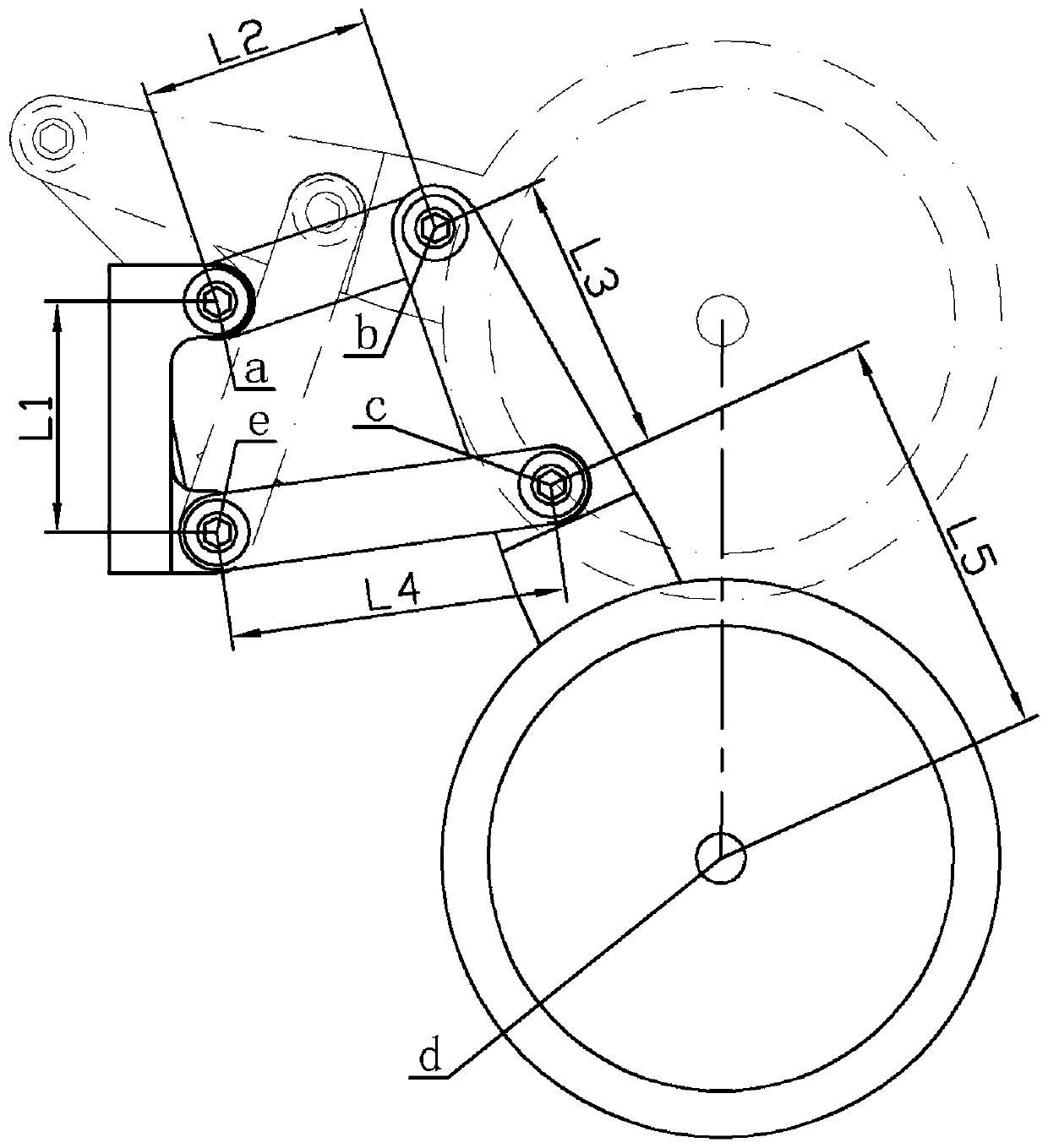
[0030] Hawken linear mechanism 2 includes connecting rod I21, connecting rod II22 and connecting rod III23, connecting rod II22 is hinged between the upper end of connecting rod I21 and the upper end of fixed bracket 1 through a pin shaft, and connecting rod III23 is hinged at the middle of connecting rod I21 through a pin shaft Between the lower end of the fixed bracket 1, the connecting rod III23 is arranged below the connecting rod II22, and the length of the connecting rod III23 is longer than that of the connecting rod II22.

[0031] The wheel shaft 3 adopts a stepped shaft and is ve...


PUM


Abstract

The invention discloses a displacement detection wheel, a robot chassis and a movable robot. The displacement detection wheel comprises a fixed support, an axle and a displacement wheel rotationally installed on the axle. The end face of the axle is in rigid connection with a magnetoelectric encoder. The displacement wheel is in rigid connection with a strong magnet arranged face to face with themagnetoelectric encoder at an interval. The axle is connected with the fixed support through a Hawken linear mechanism. A torsional spring used for pushing the displacement wheel to be tightly attached to the ground is connected between the Hawken linear mechanism and the fixed support. According to the displacement detection wheel, the displacement wheel is free of transverse displacement duringupward movement through the Hawken linear mechanism, and the displacement detection wheel can be installed conveniently on the premise that an existing regional space is not changed; force is applieddownwards to the displacement wheel through the torsional spring, the displacement wheel is tightly attached to the ground, and then slipping of the displacement wheel can be effectively avoided; andthe strong magnet and the magnetoelectric encoder are installed on the displacement wheel and the axle, the displacement of the robot is measured by the magnetoelectric encoder, and the cost is low.

Description

technical field [0001] The invention relates to the field of autonomous mobile robots, in particular to a displacement detection wheel, a robot chassis and a mobile robot. Background technique [0002] A mobile robot is a comprehensive system integrating environmental perception, dynamic decision-making and planning, behavior control and execution. It integrates multi-disciplinary research results in sensor technology, information processing, electronic engineering, computer engineering, automation control engineering, and artificial intelligence. It represents the highest achievement of mechatronics and is one of the most active fields of science and technology development. With the continuous improvement of robot performance, the application range of mobile robots has been greatly expanded, not only in industry, agriculture, medical care, service and other industries, but also in harmful and dangerous occasions such as urban security, national defense and space detection. ...

Claims


Application Information

Patent Timeline
Patent Type & Authority Applications(China)
IPC IPC(8): B25J9/00B25J5/00B62D57/02G01B7/02
CPCB25J5/00B25J5/007B25J9/00B25J9/0009B62D57/02G01B7/02
Inventor 蔡佳豪李金波明振
Owner 湖南合控智能技术有限公司
Why Eureka
Try Eureka