A plastic handle positioning and feeding device and a bronzing machine using the device

A feeding device and handle technology, which is applied to conveyors, rotary conveyors, printing machines, etc., to achieve the effect of increasing the degree of automation, reducing labor intensity and improving the efficiency of automatic operation

Active Publication Date: 2021-10-22
HANGZHOU UNITED TOOLS CO LTD
View PDF21 Cites 0 Cited by
  • Summary
  • Abstract
  • Description
  • Claims
  • Application Information

AI Technical Summary

Problems solved by technology

However, this invention only involves the automatic conveying of workpieces, and does not propose a solution that is conducive to improving work efficiency in the loading and unloading link

Method used


Image

  • A plastic handle positioning and feeding device and a bronzing machine using the device
  • A plastic handle positioning and feeding device and a bronzing machine using the device
  • A plastic handle positioning and feeding device and a bronzing machine using the device

Examples


Embodiment 1

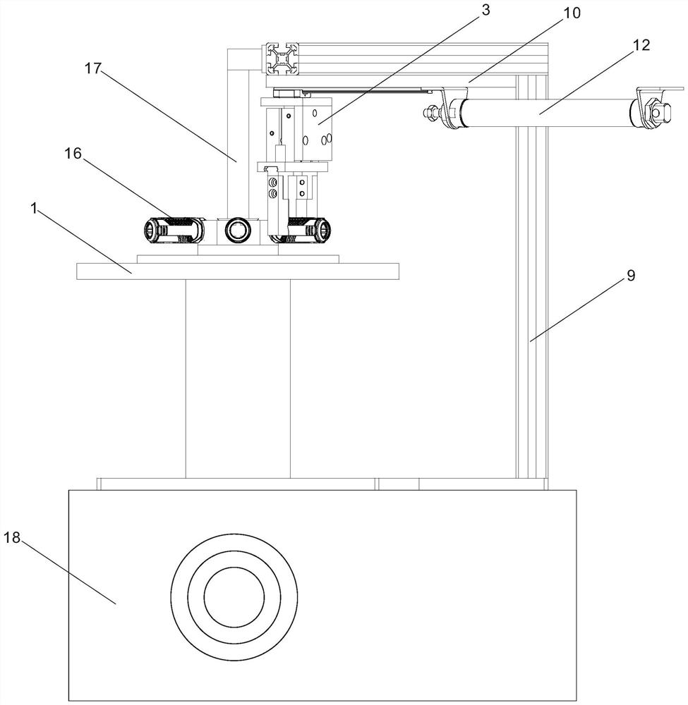
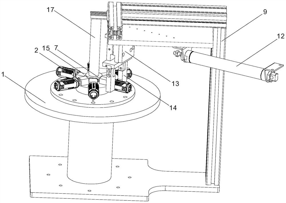
[0026] like figure 1 , figure 2 , Figure 4 to Figure 6As shown, a plastic handle positioning and feeding device is used for hot stamping machines with screwdriver plastic handles. The plastic handle positioning and feeding device includes an intermittently moving split turntable 1, a workpiece support 2 and a discharge chuck 3. There are six workpiece supports 2 and they are radially distributed on the split turntable 1. The split turntable 1 Every turn 60 ° pauses 0.8 seconds, promptly divides turntable 1 to have six intermittent pause points. Set the intermittent pause point corresponding to the loading position as position 1, clockwise, followed by position 2, position 3, position 4, position 5 and position 6, the discharge position In position six. The unloading chuck 3 is connected to a reciprocating mechanism located next to the dividing turntable 1. The unloading chuck 3 corresponds to the discharge position of the dividing turntable 1, that is, the sixth position...

Embodiment 2

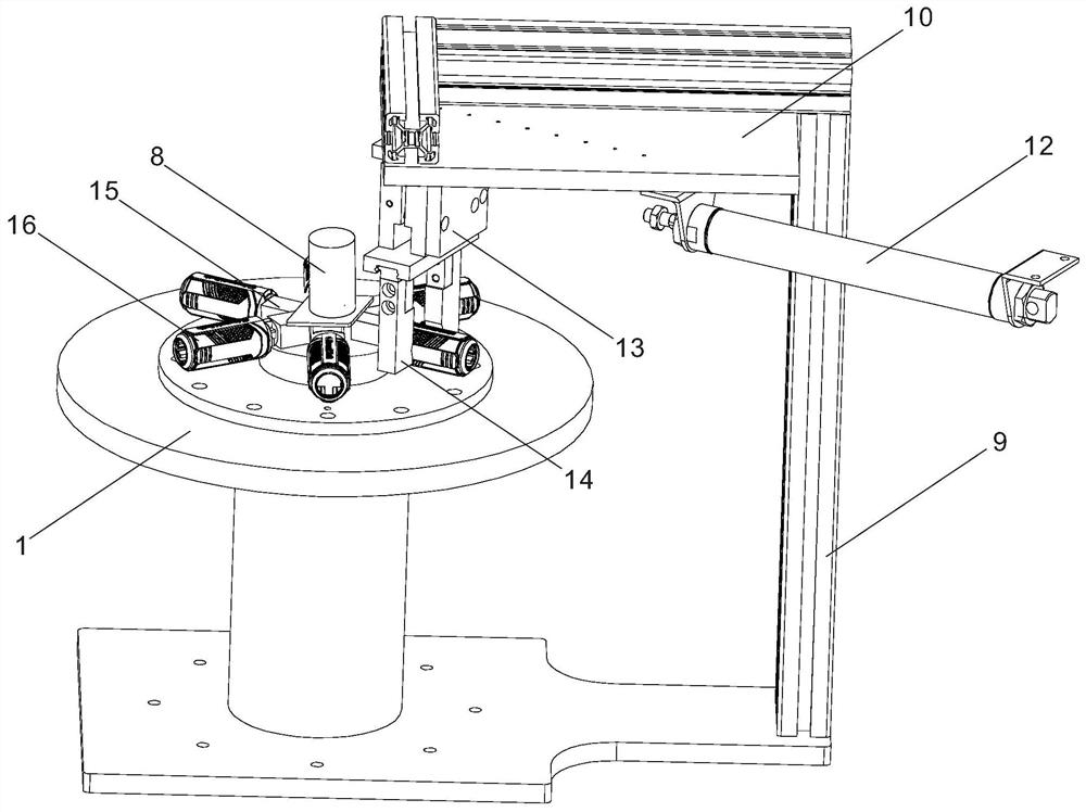
[0030] like image 3 As shown, the rotation drive mechanism includes a rotation drive motor 8, the rotation drive motor 8 is located at the center of the top of the split turntable 1, and is fixed to the top of each substrate mounting seat 15, the output end of the rotation drive motor 8 is provided with a driving bevel gear, and the workpiece support body A bevel gear 6 is fixed at the inner end of the base body 4 , and the bevel gear is driven to mesh with the bevel gear 6 . The bottom end of the center shaft of the dividing turntable 1 is fixedly connected with the output end of a geared motor. All the other are with embodiment 1.

[0031] Through program setting, every time the split turntable 1 rotates one step, that is, the angle of 60°, the rotation drive motor also drives the bevel gear 6 to rotate 60° by driving the bevel gear, so that the workpiece support base 4 and even the workpiece 16 on it rotate 60° by itself. .

Embodiment 3

[0033] There are eight workpiece supports 2, and the dividing turntable 1 has eight intermittent pause points, which are set as positions 1 to 8, the loading position is at position 1, and the unloading position is at position 8. There are two hot stamping devices, corresponding to the third position and the seventh position of the divided turntable 1, which can complete double-sided hot stamping. All the other are with embodiment 2.

[0034] Through the program setting, every time the split turntable 1 rotates one step, that is, at an angle of 45°, the rotation drive motor also drives the bevel gear 6 to rotate 45° by driving the bevel gear, so that the workpiece support base 4 and even the workpiece 16 on it rotate 45°. .


PUM


Abstract

The invention discloses a plastic handle positioning and feeding device, which comprises an intermittently moving dividing turntable, a workpiece support body and a discharge chuck. On the reciprocating mechanism, the unloading chuck corresponds to the discharge position of the dividing turntable, and the unloading chuck is electrically connected to a controller. The invention also provides a bronzing machine using the device. When the present invention works, the plastic handle workpiece is loaded on the workpiece support body, and is positioned on the workpiece support body. As the dividing turntable rotates, the workpiece is transported to different positions and pauses intermittently. During the intermittent pause, it accepts bronzing, printing or other The processing of the surface processing device is finally automatically unloaded from the dividing turntable through the unloading chuck. The plastic handle positioning and feeding device can improve the efficiency of automatic operation, improve work efficiency, liberate labor to a certain extent, and reduce labor intensity of personnel.

Description

technical field [0001] The invention relates to a tool processing equipment, more specifically, it relates to a plastic handle positioning feeding device and a bronzing machine using the device. Background technique [0002] Many hand tools are equipped with detachable plastic handles. In order to highlight the brand grade or enhance the visual effect of the appearance, tool manufacturers often carry out hot stamping on the outer surface of the plastic handle. The existing plastic handle bronzing processing equipment has low automatic operation efficiency. During operation, it mainly relies on manually picking and placing workpieces on the equipment to complete loading, unloading and positioning. The work efficiency is low and the labor intensity is high. If the plastic handle has multi-sided hot stamping requirements, the operator needs to change the surface manually, which makes the operation more difficult and puts forward higher requirements for the physical strength and...

Claims


Application Information

Patent Timeline
Patent Type & Authority Patents(China)
IPC IPC(8): B41F19/06B65G29/00
CPCB41F19/062B41P2219/43B65G29/00
Inventor 李井建欧阳忠
Owner HANGZHOU UNITED TOOLS CO LTD
Why Eureka
Try Eureka