Automatic trimming method for stamping die

A technology of stamping dies and stamping dies, which is applied in the field of automatic edge trimming of stamping dies, can solve the problems of prolonging the production cycle of workpieces and reducing processing efficiency, and achieve the effect of shortening the production cycle and improving production efficiency

Pending Publication Date: 2022-07-08
赣州佳广智能装备科技有限公司
View PDF0 Cites 0 Cited by
  • Summary
  • Abstract
  • Description
  • Claims
  • Application Information

AI Technical Summary

Problems solved by technology

As a basic industry, the quality, precision and life of molds play a very important role in the development of other industries. It is called "the mother of industry" in the world. Existing molds are divided into stamping molds, hot forging molds, plastic molds, Casting molds, rubber molds and glass molds, etc. Among them, cold stamping molds are widely used and mature in technology, and account for the largest proportion in various molds. There are still some problems that need to be further improved. The main reason is that after the existing stamping die stamps the inside of the thin plate, the excess material on the edge of the plate needs to be trimmed separately, which greatly prolongs the production cycle of the workpiece , reducing the processing efficiency, in view of the above problems, the present invention provides an automatic edge trimming device for stamping dies and an edge trimming method thereof

Method used


Image

  • Automatic trimming method for stamping die
  • Automatic trimming method for stamping die
  • Automatic trimming method for stamping die

Examples


Embodiment Construction

[0031] The technical solutions in the embodiments of the present invention will be clearly and completely described below with reference to the accompanying drawings in the embodiments of the present invention. Obviously, the described embodiments are only a part of the embodiments of the present invention, rather than all the embodiments. Based on the embodiments of the present invention, all other embodiments obtained by those of ordinary skill in the art without creative efforts shall fall within the protection scope of the present invention.

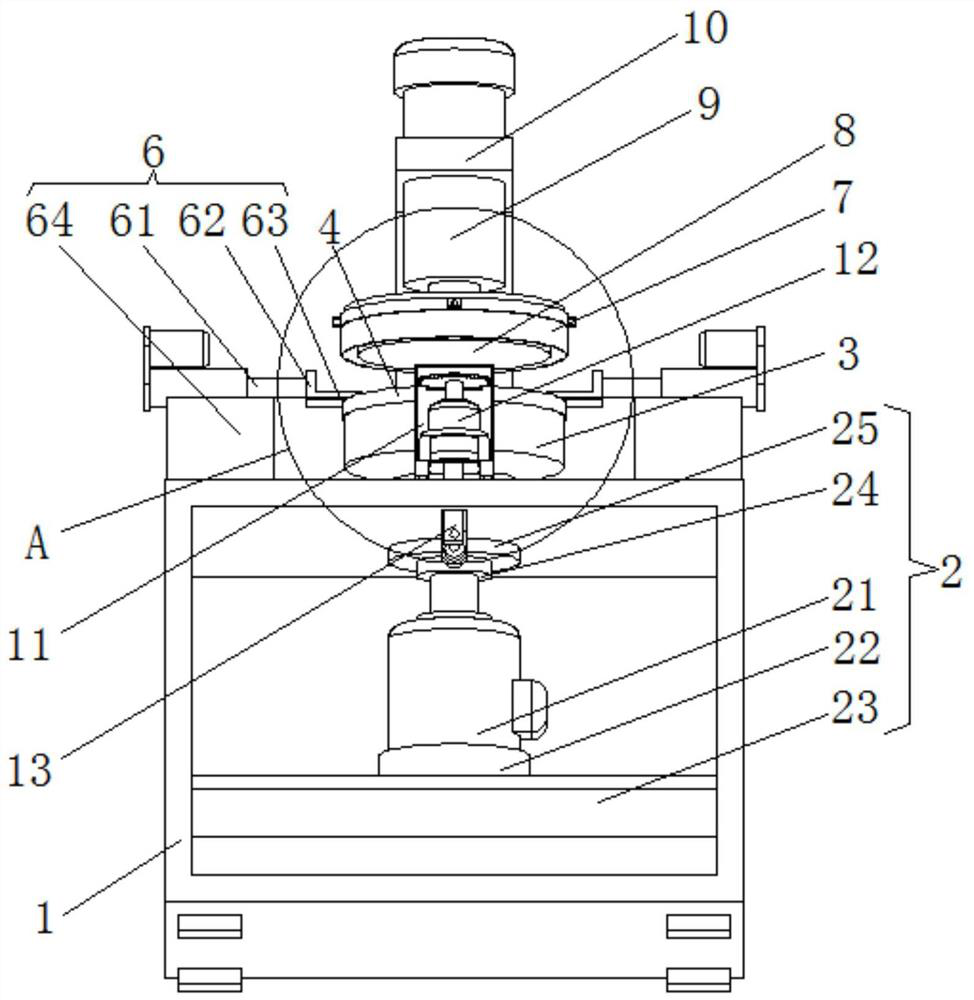
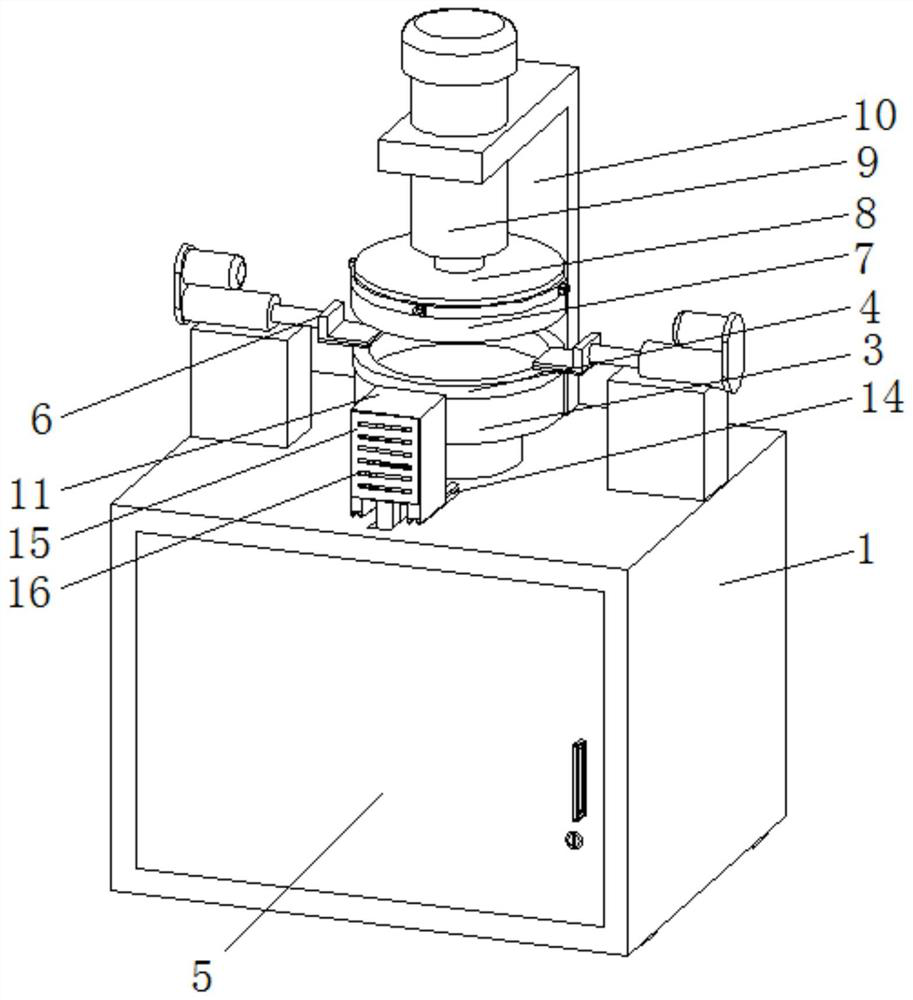
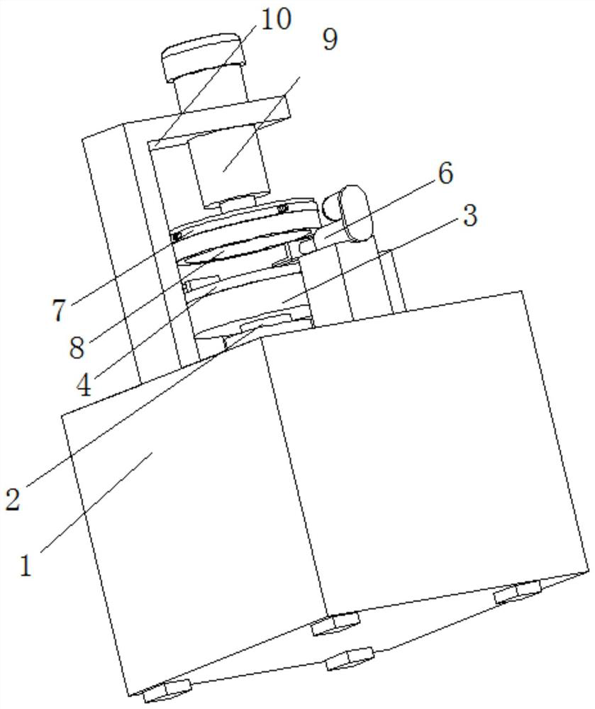
[0032] see Figure 1-6, an automatic edge trimming device for stamping die, comprising a support box 1, a box door 5 is hingedly installed on the inner side of the front side of the support box 1, and a handle is fixedly installed on one side of the front side of the box door 5, and the box door 5 is opposite to the support box body. 1. The internal subsequent installation structure is sealed and protected to avoid contact and adjust...


PUM


Abstract

The invention relates to the technical field of stamping processing equipment, and discloses an automatic trimming method for a stamping die, which comprises a supporting box body, the inner side of the middle part of the supporting box body is fixedly sleeved with a rotary positioning mechanism, the top surface of the rotary positioning mechanism is fixedly provided with a lower stamping die, and the lower stamping die is internally and movably sleeved with a workpiece; the two sides of the top face of the workpiece are movably connected with constant pressure mechanisms, the bottom faces of the constant pressure mechanisms are fixedly connected to the top face of the middle of the supporting box body, a lower pressing sleeve is arranged at the top of the workpiece, and the inner side of the top of the lower pressing sleeve is fixedly connected with an upper stamping die in a sleeved mode. According to the automatic edge cutting device for the stamping die and the edge cutting method of the automatic edge cutting device, through mutual cooperation of the constant pressure mechanism, the adjusting composite box body, the edge cutting mechanism and the advancing mechanism, redundant materials of a workpiece are subjected to automatic edge cutting operation after the workpiece is stamped, the integrated stamping and edge cutting machining technology is achieved, the production cycle of the workpiece is shortened, and the production efficiency is improved.

Description

technical field [0001] The invention relates to the technical field of stamping processing equipment, in particular to an automatic edge trimming method for a stamping die. Background technique [0002] Moulds are the basic process equipment for industrial products such as machinery, automobiles, electronics, communications, and home appliances, and are high-tech products. As a basic industry, the quality, precision and life of molds play a very important role in the development of other industries. They are called "the mother of industry" internationally. The existing molds are divided into stamping molds, hot forging molds, plastic molds, Casting molds, rubber molds and glass molds, etc. Among them, cold stamping molds are widely used and mature in technology, and account for the largest proportion of various molds, but the structure of the existing stamping molds on the trimming function is in the actual production process. There are still some problems that need to be f...

Claims


Application Information

Patent Timeline
Patent Type & Authority Applications(China)
IPC IPC(8): B21D22/02B21D19/00B21D37/10B21D43/00B23P23/04
CPCB21D22/02B21D19/005B21D37/10B21D43/003B23P23/04Y02P40/57
Inventor 不公告发明人
Owner 赣州佳广智能装备科技有限公司
Why Eureka
Try Eureka