Electric automobile regenerative braking control method

A technology for electric vehicles and regenerative braking force, which is applied in electric vehicles, electric braking systems, vehicle components, etc., and can solve problems such as wheel locking, poor driver feeling and energy recovery, and reduced braking safety

Inactive Publication Date: 2020-02-21
江苏航运职业技术学院
View PDF3 Cites 17 Cited by
  • Summary
  • Abstract
  • Description
  • Claims
  • Application Information

AI Technical Summary

Problems solved by technology

The braking system based on the parallel regenerative braking control strategy is mainly based on friction braking and supplemented by regenerative braking. It has a simple structure and high practical application value, but the disadvantage is that the driver's feeling and energy recovery are not good.
And neither of the two control strategies considers the adhesion coefficient, especially when braking on roads with low adhesion coefficient (water, ice and snow), increasing the regenerative braking force can easily lead to wheel locking and reduce braking safety

Method used

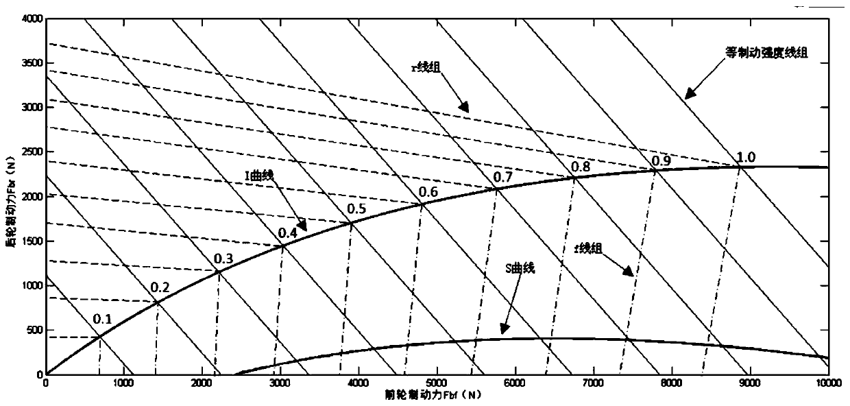
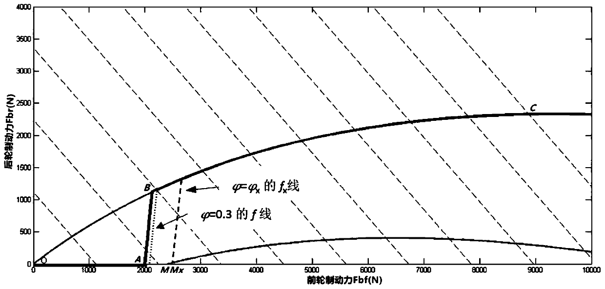
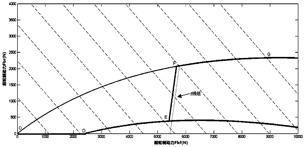

Image

  • Electric automobile regenerative braking control method
  • Electric automobile regenerative braking control method
  • Electric automobile regenerative braking control method

Examples


Embodiment Construction

[0063] The present invention will be further described below in conjunction with the accompanying drawings.

[0064] The electric vehicle regenerative braking control method comprises the following steps: Step 1. Set up a road surface eigenvalue calculation method based on the adhesion system, establish a semi-empirical mathematical model of adhesion coefficient and slip rate, introduce the road surface state eigenvalue, identify the road surface condition and the corresponding road surface average adhesion coefficient. Concretely comprise the following steps: step a. according to Burckhardt model, Kiencke model, set up the mathematical model of wheel, introduce slip rate s to represent the ratio of slip component in the wheel motion process, be defined as:

[0065]

[0066] In the formula, ω d is the wheel angular velocity (rad / s); r d is the rolling radius of the wheel (m); V tire is the longitudinal rolling speed of the wheel (m / s);

[0067] When the wheel is purely ...


PUM


Abstract

The invention discloses an electric automobile regenerative braking control method. The electric automobile regenerative braking control method comprises the steps that a pavement characteristic valuecalculation method is established based on an attachment system, a semi-empirical mathematical model of an attachment coefficient and a sliding rate is established, a pavement state characteristic value is introduced, and the pavement condition and an average adhesion coefficient corresponding to the pavement are identified; the braking forces of the front and rear wheels are judged according tothe size of the adhesion coefficient and the brake strength; the braking strength, the battery SOC and the vehicle speed are used as inputs of a fuzzy controller, an empirical fuzzy rule is established, the proportion of the regenerative braking force to the front wheel braking force is output through the fuzzy controller, and the final regenerative braking force is obtained by comparing the regenerative braking force with the maximum torque output by the motor; and the maximum braking force which can be provided by the motor is determined according to the final regenerative braking force, andthe front wheel friction braking force is obtained. According to the electric automobile regenerative braking control method, on the premise that braking safety is guaranteed, front and rear wheel braking force, the motor braking force and the friction braking force are reasonably distributed according to different attachment coefficients, the braking energy recovery rate and the driving range are improved, and the braking safety is increased.

Description

technical field [0001] The invention relates to the field of electric vehicles, in particular to a regenerative braking control method for electric vehicles. Background technique [0002] Among the key technologies of the electric vehicle power system, the rationality of the control strategy will directly affect the performance level of the vehicle. Compared with fuel vehicles, the energy utilization rate of the pure electric vehicle power system is relatively high. Through reasonable regenerative braking The control strategy can effectively improve the recovery rate of braking energy, further improve the efficiency of the vehicle, and effectively reduce vehicle pollutant emissions and save oil. At the same time, a reasonable control strategy can improve the service life of the power battery, extend the driving range of electric vehicles, and reduce the risk of high costs caused by premature battery scrapping. An important part of R&D and performance testing. [0003] The ...

Claims


Application Information

Patent Timeline
Patent Type & Authority Applications(China)
IPC IPC(8): B60L7/10
CPCB60L7/10
Inventor 王昕灿孙旭王锦华王皆佳郑燕萍吕立亚
Owner 江苏航运职业技术学院
Why Eureka
Try Eureka