Automobile integrated brake-by-wire system

A technology of integrated lines and wheel brakes, applied in the direction of brakes, brake transmissions, vehicle components, etc., can solve the problems of high production cost and large occupied space, achieve low production cost, reduce occupied space, and improve modularization degree of effect

Active Publication Date: 2013-09-18
ZHEJIANG WANXIANG PRECISION IND +1
View PDF8 Cites 7 Cited by
  • Summary
  • Abstract
  • Description
  • Claims
  • Application Information

AI Technical Summary

Problems solved by technology

[0007] The third purpose of the present invention is to overcome the problems of large space occupation and high manufacturing cost of the energy storage device that combines hydraulic braking and electronic braking to achieve the effect of emergency hydraulic braking, and provides a A car integrated brake-by-wire system that can realize the combination of the energy storage device and the brake master cylinder to reduce the space occupied by the brake system and reduce the cost; and when the brake-by-wire brake fails, it can also realize conventional hydraulic braking

Method used


Image

  • Automobile integrated brake-by-wire system
  • Automobile integrated brake-by-wire system
  • Automobile integrated brake-by-wire system

Examples


Embodiment 1

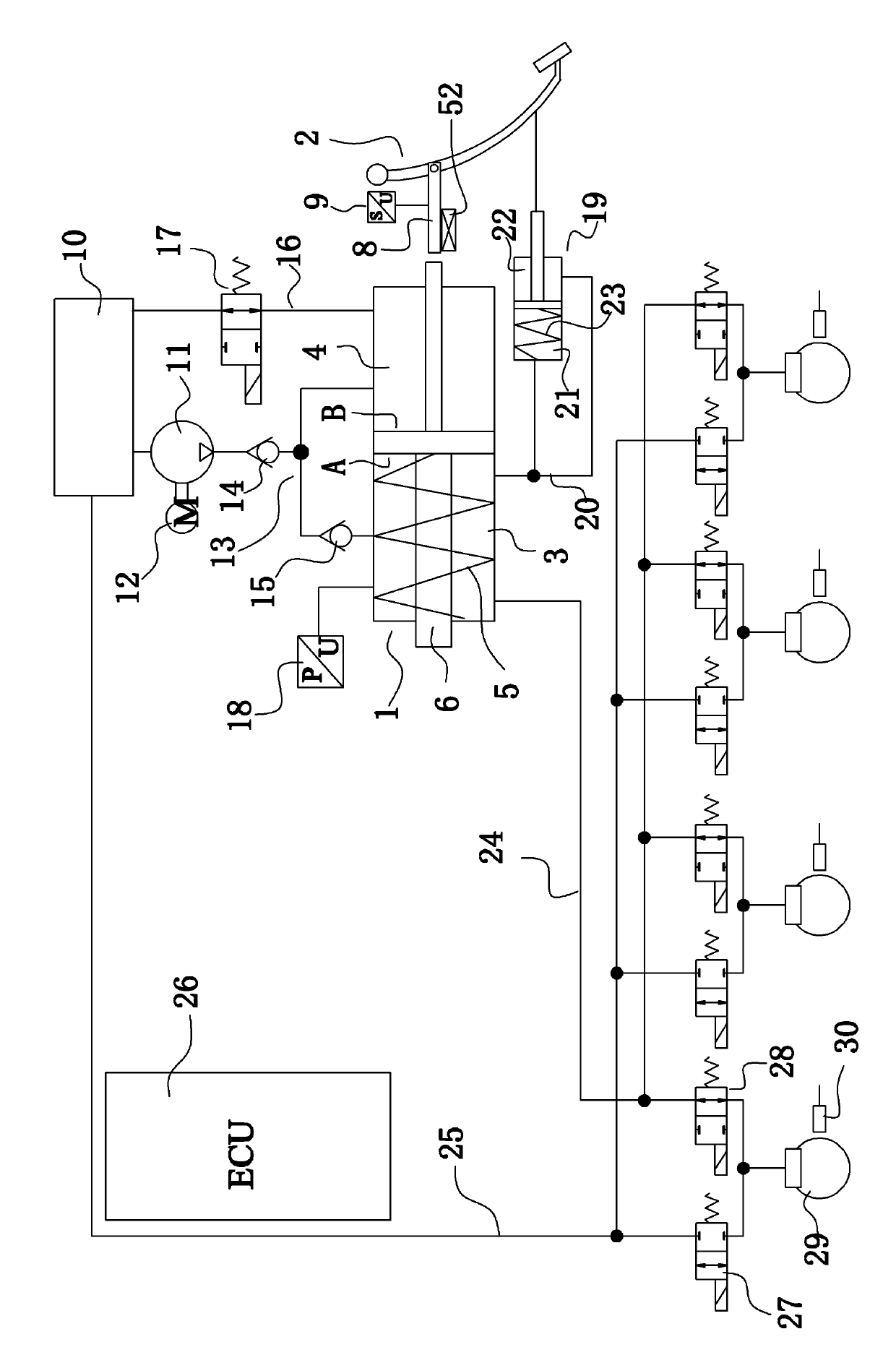
[0035] Embodiment 1: as figure 1 As shown, an automobile integrated brake-by-wire system includes an electronic control unit 26, a brake fluid tank 10, a motor 12, a pump 11, a brake master cylinder 1, a brake pedal 2, a wheel brake 29 and a The speedometer 30. A stroke sensor 9 is arranged on the brake pedal 2 . Both sides of the piston on the master brake cylinder 1 are provided with a working chamber 3 and a fluid replenishing chamber 4 . A first return spring 5 is arranged in the working chamber; a pressure sensor 18 for detecting the pressure of the working chamber is arranged on the working chamber.

[0036] A first brake passage 24 connects the brake master cylinder 1 and the wheel brake 29 . The first brake passage 24 includes a first main passage connected to the working chamber 3 and first branch passages respectively connected to the wheel brakes 29 . The first brake passage 24 is provided with a first electromagnetic switch valve 28; specifically, each first br...

Embodiment 2

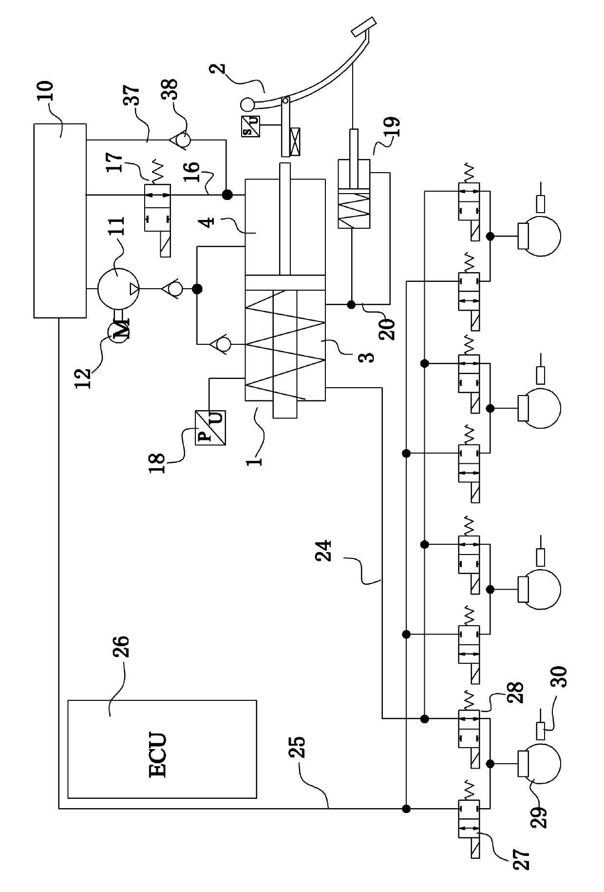
[0048] Embodiment 2: as image 3 As shown, a sixth brake passage 37 is provided between the brake fluid tank 10 and the brake master cylinder 1 , which connects the brake fluid tank 10 and the liquid replenishing chamber 4 . The sixth brake passage 37 is provided with a first one-way valve 38 through which the brake fluid can flow from the brake fluid tank to the liquid replenishing chamber. Refer to Embodiment 1 for the rest of the structure of this embodiment.

[0049] When the brake-by-wire system breaks down, specifically, when the electronic control unit 26 works normally but the motor 12 or the pump 11 breaks down, conventional hydraulic braking can be realized through the cooperation of the sixth brake passage 37 and the first one-way valve 38. At the same time, when the brake-by-wire system works normally, it will not affect the brake-by-wire. Since the flow direction of the first one-way valve 38 is from the brake fluid tank to the liquid replenishment chamber, the ...

Embodiment 3

[0050] Embodiment 3: as Figure 4 , Figure 5 As shown, one end of the brake master cylinder 1 is provided with an energy storage chamber 39 and the energy storage chamber communicates with the working chamber 3 . The energy storage cavity 39 is provided with a piston and an energy storage spring 51 . The energy storage chamber 39 communicates with the working chamber 3 through a plurality of guide holes 50 . The guide rod arranged on the piston of the brake master cylinder passes through the working chamber 3 and the energy storage chamber 39 and is located outside the brake master cylinder, and a sealing ring is arranged between the guide rod and the cylinder body of the brake master cylinder. The distance L between the first fluid replenishment hole 7 of the brake master cylinder and the inner end surface of the sealing end cover 33 is greater than the piston thickness of the brake master cylinder.

[0051] Such as Figure 4 As shown, the first brake passage 24 is provi...


PUM


Abstract

The invention discloses an automobile integrated brake-by-wire system, and provides a brake system which can realize the brake-by-wire, can also realize conventional hydraulic brake when the brake-by-wire fails and simultaneously has the characteristics of short brake distance and small occupied space. The automobile integrated brake-by-wire system comprises an electronic control unit, a brake fluid tank, a pump, a brake main cylinder, a wheel brake and a brake pedal, wherein the brake pedal is provided with a stroke sensor, and a first brake passageway is connected with the brake main cylinder and the wheel brake; a second brake passageway is connected with the wheel brake and the brake fluid tank, two sides of a piston on the brake main cylinder are provided with a working cavity and a fluid complementing cavity, and the working cavity is internally provided with a first reset spring; the pump is positioned between the brake fluid tank and the brake main cylinder and is communicated with the brake fluid tank; a third brake passageway is respectively connected with the working cavity and the fluid complementing cavity through a pump outlet; and a fourth brake passageway is connected with the fluid complementing cavity and the brake fluid tank and is provided with a third electromagnetic switch valve.

Description

technical field [0001] The invention relates to an automobile brake system, in particular to an automobile integrated brake-by-wire system composed of an electronic control system and a hydraulic system. Background technique [0002] With the development of electronic control technology, electronic control technology is gradually applied to the braking system of automobiles to realize brake by wire. For the pure wire brake system, it is connected by wires, the wires transmit energy, and the data wires transmit signals to directly control the wheel brakes to achieve braking. This pure wire brake system separates the brake operation parts such as the pedal from the brake operation part such as the wheel brake, and the unpleasant vibration generated during braking will not be transmitted to the brake pedal; but its The disadvantage is that once the electronic control fails, the entire braking system will be paralyzed. [0003] Further, in order to avoid the shortcomings of th...

Claims


Application Information

Patent Timeline
Patent Type & Authority Applications(China)
IPC IPC(8): B60T13/66
Inventor 孙国辉潘文标潘劲刘伟资小林张杰
Owner ZHEJIANG WANXIANG PRECISION IND
Why Eureka
Try Eureka