
Cup holder device for new energy automobile

A technology of new energy vehicles and cup holders, which is applied to the special position of the vehicle, vehicle parts, transportation and packaging, etc. It can solve the problems of safety hazards, short circuit of wires, pouring out, etc., and achieve the effect of stable placement

Inactive Publication Date: 2020-02-21
崔俊
View PDF8 Cites 5 Cited by
  • Summary
  • Abstract
  • Description
  • Claims
  • Application Information

AI Technical Summary

Problems solved by technology

[0003] During the use of the existing car cup holder device, due to the bumps of the car, the cup or bottle in the cup holder device will be subject to a great impact, causing the cup or bottle to pour out from the cup holder, and if the cup is filled with heat Water can easily scald the driver or passengers, causing a lot of trouble to the driver or passengers. At the same time, the water in the cup may even short-circuit the wires, which is likely to cause safety hazards

Method used


Image

  • Cup holder device for new energy automobile
  • Cup holder device for new energy automobile
  • Cup holder device for new energy automobile

Examples


Embodiment 1

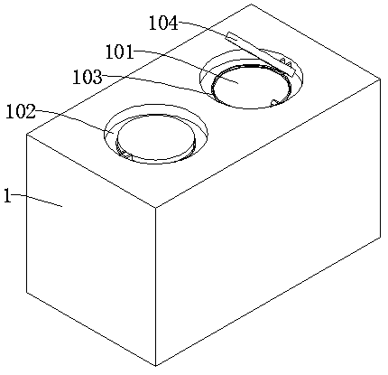
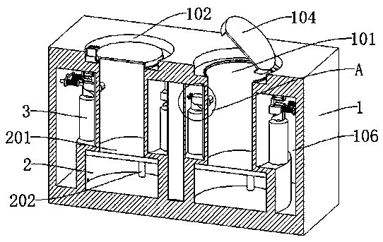
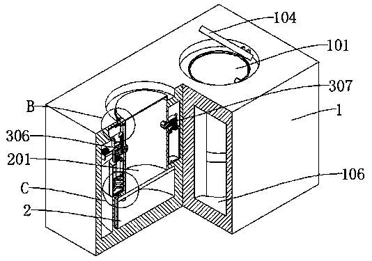
[0037] refer to Figure 1-9 , a cup holder device for new energy vehicles, comprising a cup holder body 1, a placement groove 101 is dug in the cup holder body 1, a first air cylinder 2 is provided at the bottom of the placement groove 101, and a first piston is connected inside the first air cylinder 2 201, the first piston 201 is slidably connected to the inner wall of the first air cylinder 2 through the guide rod 202;

[0038] There is also a cavity 106 dug in the cup holder body 1, and two mutually symmetrical second air cylinders 3 are connected to the inner wall of the cavity 106, and the first air cylinder 2 and the second air cylinder 3 are connected through a connecting pipe 203;

[0039] Both the second air cylinders 3 are slidably connected with a sliding rod 304, the top of the sliding rod 304 is connected with a first slider 305, and the placement groove 101 is respectively slidably connected with a second slider 306 that cooperates with the first slider 305 and...

Embodiment 2

[0052] refer to Figure 1-9 , a cup holder device for new energy vehicles, comprising a cup holder body 1, a placement groove 101 is dug in the cup holder body 1, a first air cylinder 2 is provided at the bottom of the placement groove 101, and a first piston is connected inside the first air cylinder 2 201, the first piston 201 is slidably connected to the inner wall of the first air cylinder 2 through the guide rod 202;

[0053] There is also a cavity 106 dug in the cup holder body 1, and two mutually symmetrical second air cylinders 3 are connected to the inner wall of the cavity 106, and the first air cylinder 2 and the second air cylinder 3 are connected through a connecting pipe 203;

[0054] Both the second air cylinders 3 are slidably connected with a sliding rod 304, the top of the sliding rod 304 is connected with a first slider 305, and the placement groove 101 is respectively slidably connected with a second slider 306 that cooperates with the first slider 305 and...


PUM


Abstract

The invention discloses a cup holder device for a new energy automobile, and belongs to the technical field of automobile cup holders. The cup holder device for the new energy automobile comprises a cup holder body, wherein a placement groove is formed in the cup holder body; a first air cylinder is arranged at the bottom of the placement groove; a first piston is connected in the first air cylinder; two mutually symmetrical second air cylinders are connected to the inner wall of a cavity; the first air cylinder communicates with the second air cylinders through connecting pipelines; sliding rods are slidably connected in the two second air cylinders; first sliding blocks are connected to the tops of the sliding rods; second sliding blocks and third sliding blocks which are matched with the first sliding blocks are slidably connected in the placement groove; and push blocks matched with a cover plate are connected to the tops of the first sliding blocks. The cup holder device for the new energy automobile is convenient to use, and the top of the placement groove can be hermetically connected while a water cup is clamped, so that the water cup is prevented from toppling, meanwhile,water in the water cup is prevented from spilling, and potential safety hazards are avoided.

Description

technical field [0001] The invention relates to the technical field of buttoning anti-flammation cloth, in particular to a cup holder device for a new energy vehicle. Background technique [0002] New energy vehicles refer to the use of unconventional vehicle fuels as power sources (or the use of conventional vehicle fuels and new vehicle power devices), and the comprehensive vehicle power control and advanced technology in driving, the formation of advanced technical principles, with Automobiles with new technology and new structure, new energy vehicles include four types of hybrid electric vehicles, pure electric vehicles, fuel cell electric vehicles and other new energy vehicles, etc. The promotion of new energy vehicles is to meet the needs of environmental protection and oil crisis, reduce or Abandon the current mainstream models that burn traditional gasoline or diesel powered internal combustion engines. [0003] During the use of the existing car cup holder device, ...

Claims


Application Information

Patent Timeline
Patent Type & Authority Applications(China)
IPC IPC(8): B60N3/10
CPCB60N3/10B60N3/106B60N3/108
Inventor 崔俊
Owner 崔俊
Learn More