Universal unmanned underwater vehicle recovery device and recovery method

A recovery device and submersible technology, applied in lifting devices, transportation and packaging, underwater operation equipment, etc., can solve problems such as weak wind and wave resistance of small floating docks, difficulty in recovering unmanned submersibles, and injuries to staff and equipment. , to achieve the effect of easy operation and maintenance, good balance and improved safety

Active Publication Date: 2020-02-21
JIANGSU UNIV OF SCI & TECH +1
View PDF7 Cites 9 Cited by
  • Summary
  • Abstract
  • Description
  • Claims
  • Application Information

AI Technical Summary

Problems solved by technology

[0002] With the development of science and technology, there are more and more explorations of marine resources. As the main exploration tool, unmanned submersibles need to recover and collect data after completing operations. However, the marine environment is complex and changeable, especially in harsh sea conditions. The recovery of unmanned submersibles has become very difficult
[0003] There are two main recovery methods. The first one is that the staff take a small boat close to the unmanned submersible, dock with the artificially assisted lifting device, and complete the recovery. This recovery method is greatly affected by wind and waves, and the risk factor is poor when the sea condition is poor. High, it is easy to cause injury to staff and equipment; the second is to use floating docks and lifting platforms for underwater docking recovery, which can reduce the impact of wind and waves, but small floating docks have weak wind and wave resistance, and large floating docks The cost is high, the mother ship needs special support, the recycling fee is expensive, and it is not suitable for popular use

Method used


Image

  • Universal unmanned underwater vehicle recovery device and recovery method
  • Universal unmanned underwater vehicle recovery device and recovery method
  • Universal unmanned underwater vehicle recovery device and recovery method

Examples


Embodiment Construction

[0026] The present invention will be described in further detail below in conjunction with the accompanying drawings.

[0027] In order to make the object, technical solution and advantages of the present invention clearer, the present invention will be further described in detail below in conjunction with the accompanying drawings and specific embodiments. The following examples can enable those skilled in the art to understand the present invention more comprehensively, but the present invention is not limited to the scope of the described examples.

[0028] The recovery device of the unmanned submersible of the present invention is a powerless recovery device, and has two working modes of 30-meter underwater recovery and water surface recovery.

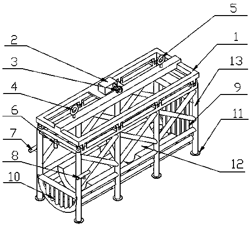
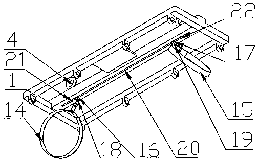
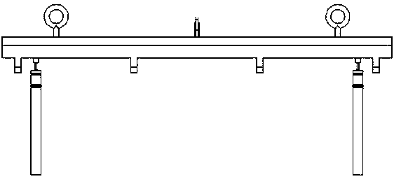
[0029] Such as Figure 1-Figure 8 As shown, the present specific embodiment adopts the following technical scheme: comprising a cage body 13 and a top crossbeam 1; the top crossbeam 1 has a side beam and a middle crossbeam, and th...


PUM


Abstract

The invention discloses a universal unmanned underwater vehicle recovery device and recovery method, and relates to the technical field of underwater robot recovery. The device comprises a cage and atop cross beam. A first lifting lug, a second lifting lug, a guide cable pulley and a camera cable storage box are mounted on the top cross beam, and the top cross beam and the cage are fixedly connected to form a recovery lifting cage. A front fence and a rear fence are arranged at the two ends of the cage correspondingly. A left eye camera and a right eye camera are mounted on the two sides of an inlet of the cage. A top camera is mounted at the top of the inlet of the cage. A T-shaped groove is formed in the bottom of a middle cross beam of the top cross beam. A spherical hinge structure isin sliding connection in the T-shaped groove. The top cross beam is connected with hose clamps through the spherical hinge structure. The universal unmanned underwater vehicle recovery device and recovery method have the advantages that the two work modes of water recovery and underwater recovery are achieved, the proper work modes can be selected according to different work sea conditions, and work efficiency is improved; and the problem of high danger of release and recovery work of unmanned underwater vehicles can be solved.

Description

technical field [0001] The invention relates to the technical field of underwater robot recovery, in particular to a universal unmanned submersible recovery device and recovery method. Background technique [0002] With the development of science and technology, there are more and more explorations of marine resources. As the main exploration tool, unmanned submersibles need to recover and collect data after completing operations. However, the marine environment is complex and changeable, especially in harsh sea conditions. The recovery of unmanned submersibles has become very difficult. [0003] There are two main recovery methods. The first one is that the staff take a small boat close to the unmanned submersible, dock with the artificially assisted lifting device, and complete the recovery. This recovery method is greatly affected by wind and waves, and the risk factor is poor when the sea condition is poor. High, it is easy to cause injury to staff and equipment; the se...

Claims


Application Information

Patent Timeline
Patent Type & Authority Applications(China)
IPC IPC(8): B63C11/52B63B23/00B63B23/48
CPCB63C11/52B63B23/00B63B23/48Y02A40/81
Inventor 王佳朱佳佳卢道华雍惠
Owner JIANGSU UNIV OF SCI & TECH
Why Eureka
Try Eureka