A Downhole Pulse Generation Device and Injection Method Driven by Tubing Transmission

A pulse generating device and transmission-driven technology, which is applied to vibration generating devices, drill pipes, casings, etc., can solve the problems of restricting the popularization and application of hydraulic pulse technology, the inability to realize backwashing wells, and unstable pulse frequency, etc., so as to promote comprehensive Oil displacement effect, novel design and convenient control

Active Publication Date: 2022-02-11
CHINA UNIV OF PETROLEUM (EAST CHINA) +1
View PDF5 Cites 0 Cited by
  • Summary
  • Abstract
  • Description
  • Claims
  • Application Information

AI Technical Summary

Problems solved by technology

[0002] In the past ten years, the research and application of hydraulic pulse water injection technology at home and abroad have progressed rapidly, and a series of supporting equipment and technology have been formed. The pulse generator is mainly designed with a piston structure or a solenoid valve control structure. In the actual use process Among them, the existing devices are usually greatly affected by the salinity of the injected water, mechanical impurities, scaling, etc., the working state is unstable, the life is short, the failure rate is high, or the cable is required to supply power to the underground system, the construction process is complicated, and it cannot be under pressure. Obvious defects and deficiencies such as operation and adapting to small well deviation, the application range is narrow, which limits the further popularization and application of hydraulic pulse technology
[0003] The device described in the Chinese patent document (publication number CN104929605A) includes a hydraulic pulse fracturing device. Its structure is a piston structure, and its working principle is to control the opening and closing of the nozzle through the pressure difference between the hydraulic force and the spring force. Then the pulse is excited. Due to the complex downhole environment such as fracturing sand, machine impurities, and scaling in the downhole liquid environment, the reciprocating motion of the piston itself and the sealing method are tangential structures, and the sealing method is also a rubber "0" ring seal. , prone to failure and low reliability, not suitable for long-term work in complex underground environments; at the same time relying on spring force excitation, the piston is always in the open state due to high ground pressure and cannot be reset, and loses the function of exciting pulses. The pulse frequency of this method Unstable and difficult to control, and this process is used for fracturing, cannot realize backwash well, and cannot be used in acidizing and water injection processes
[0004] At present, with the deepening of oilfield development, the demand for technologies such as wave chemical assisted production and injection, wave acidizing and plugging removal is becoming more and more urgent, and the well types (inclined wells, directional wells, horizontal wells, etc.) required to be adapted are becoming more and more complex , it is necessary to design injection devices corresponding to different well types, which has small adaptability and high investment cost

Method used


Image

  • A Downhole Pulse Generation Device and Injection Method Driven by Tubing Transmission
  • A Downhole Pulse Generation Device and Injection Method Driven by Tubing Transmission
  • A Downhole Pulse Generation Device and Injection Method Driven by Tubing Transmission

Examples


Embodiment 1

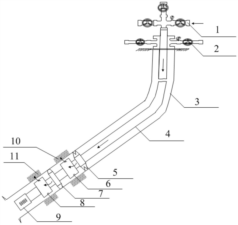
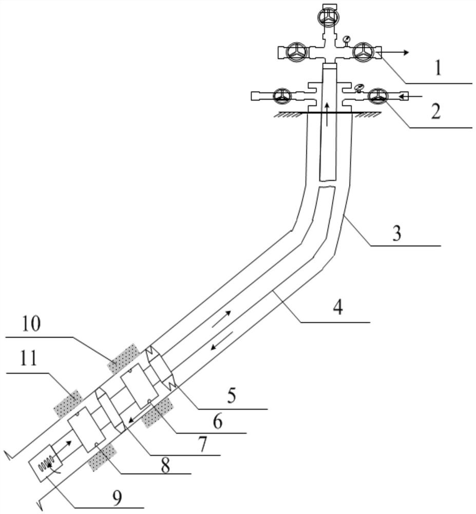
[0056] A downhole pulse generating device driven by tubing transmission, including a ground injection wellhead, the surface injection wellhead has a tubing injection end wellhead 1 and an oil-casing injection end wellhead 2, the tubing injection end wellhead 1 is connected to a tubing 4, and the tubing 4 is arranged on a casing 3 Inside, there are two hydraulic pulse generators on the tubing, a backwash valve 9 is installed at the end of the tubing, and a tubing anchoring device 5 is installed between the tubing and the casing. part. The tubing anchoring device is used to anchor the tubing on the casing of the target well to prevent the downhole tool string from shaking. The tubing anchoring device is equipped with anchor teeth, which are used to extend the tubing anchoring device when high-pressure fluid is injected into the tubing. The main body is embedded in the casing, and the high-pressure fluid in the oil pipe disappears. The anchor teeth of the oil pipe anchoring devic...

Embodiment 2

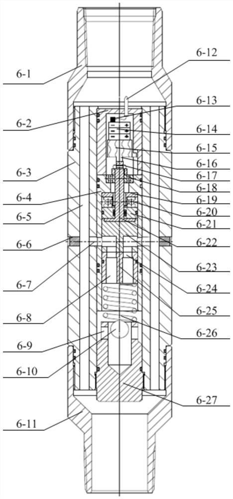
[0060] A downhole pulse generating device driven by oil pipe transmission, its structure is as described in Embodiment 1, the difference is that the hydraulic pulse generator includes an outer working cylinder 6-3, and the upper and lower ends of the outer working cylinder are provided with upper joints 6-1 , the lower joint 6-11, the outer working cylinder side wall is provided with an outer working cylinder blind plug 6-6, the outer working cylinder is provided with an inner working cylinder 6-4, and a bridge type passage is formed between the outer working cylinder and the inner working cylinder Flow channel 6-5; the fluid can be sprayed through the working cylinder, and the fluid can be passed to the next stage hydraulic pulse generator through the working cylinder for spraying.

[0061] One end of the inner working cylinder 6-4 is provided with an inner working cylinder upper joint 6-2, the other end of the inner working cylinder is provided with an inner working cylinder ...

Embodiment 3

[0066] A downhole pulse generating device driven by oil pipe transmission, its structure is as described in Embodiment 2, the difference is that a compression spring 6-26 is arranged between the fixed nozzle and the blind plug of the inner working cylinder. In actual use, it is necessary to tighten the compression spring 6-26 through the blind plug 6-27 of the working cylinder, and ensure that the fixed nozzle 6-25 is installed close to the movable nozzle 6-23 and is in a closed state. In the actual use process, it is necessary to tighten the eyelet of the outer working cylinder through the blind plug 6-6 of the outer working cylinder.


PUM


Abstract

The invention discloses a downhole pulse generating device driven by oil pipe transmission and an injection method, which belong to the technical field of oilfield development engineering and mainly include oil pipe, oil pipe anchor, hydraulic pulse generator, backwash well valve, and fluid in the hydraulic pulse generator The internal energy is stored and the pressure is boosted, and the high-pressure fluid is ejected in the form of pulses according to a certain frequency. Its pulse generating device is different from conventional hydraulic piston type generating device or electromagnetic valve device. The injection method includes: well selection of injection wells; setting of the start-up pressure value and pulse frequency of the pulse generating device, setting of the number of hydraulic pulse generators; installation of tubing and downhole tools; use of pulse wave injection to drive oil; backwashing the well. The invention is easy to install and has a simple process, and is suitable for the injection of vertical wells, inclined wells, directional wells and horizontal wells, and uses a hydraulic pulse device to provide a pulse wave with a stable frequency for the downhole oil layer. While improving the permeability near the bottom of the well, it can also Reduce residual oil saturation and greatly increase oil recovery.

Description

technical field [0001] The invention relates to a downhole pulse generating device driven by oil pipe transmission and an injection method, belonging to the technical field of oil field development engineering. Background technique [0002] In the past ten years, the research and application of hydraulic pulse water injection technology at home and abroad have progressed rapidly, and a series of supporting equipment and technology have been formed. The pulse generator is mainly designed with a piston structure or a solenoid valve control structure. In the actual use process Among them, the existing devices are usually greatly affected by the salinity of the injected water, mechanical impurities, scaling, etc., the working state is unstable, the life is short, the failure rate is high, or the cable is required to supply power to the underground system, the construction process is complicated, and it cannot be under pressure. Obvious defects and deficiencies such as operation ...

Claims


Application Information

Patent Timeline
Patent Type & Authority Patents(China)
IPC IPC(8): E21B43/16E21B28/00E21B43/00E21B23/01E21B17/10
CPCE21B43/16E21B28/00E21B43/003E21B23/01E21B17/1078
Inventor 蒲春生张鹏刘静黄飞飞康少飞李旭
Owner CHINA UNIV OF PETROLEUM (EAST CHINA)
Why Eureka
Try Eureka