Experimental system and method capable of simulating gear transmission non-inertial system environment

A gear transmission, non-inertial system technology, applied in the field of experimental systems that can simulate the gear transmission non-inertial system environment, can solve the problem of not considering the basic motion, unable to simulate the motion state of the gear transmission system, unable to provide shock and random excitation, etc.

Active Publication Date: 2020-02-21
CHONGQING UNIV
View PDF7 Cites 7 Cited by
  • Summary
  • Abstract
  • Description
  • Claims
  • Application Information

AI Technical Summary

Problems solved by technology

[0002] In a non-inertial system environment, the gear transmission system is excited by complex additional loads, its vibration characteristics will change, and even vibration instability will occur, which threatens the stable operation of the aircraft
[0003] For this reason, domestic scholars have conducted a lot of research on the dynamic characteristics of the gear transmission system during maneuvering flight through theory and have achieved many results; Motion state in flight non-inertial frame environment
[0004] In the field of aero-engine technology, th

Method used


Image

  • Experimental system and method capable of simulating gear transmission non-inertial system environment
  • Experimental system and method capable of simulating gear transmission non-inertial system environment
  • Experimental system and method capable of simulating gear transmission non-inertial system environment

Examples


Embodiment 1

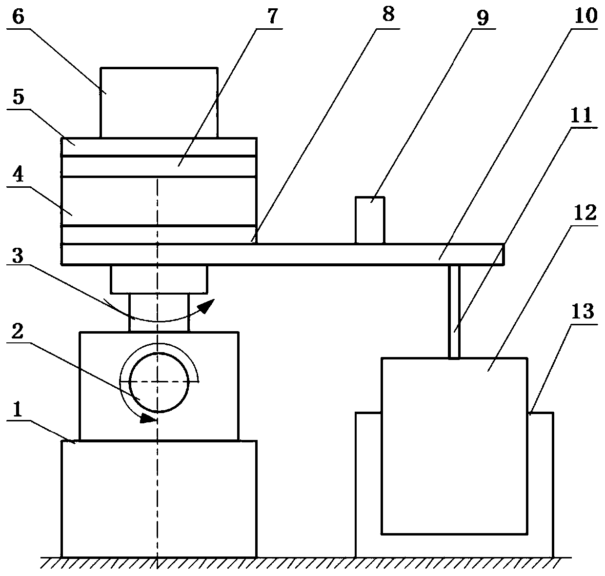
[0073] This embodiment discloses an experimental system capable of simulating a gear drive non-inertial system environment, including a gear drive experiment table 6, a manual cross slide group 5, a linear motion platform 4, and an electric vibration table 12.

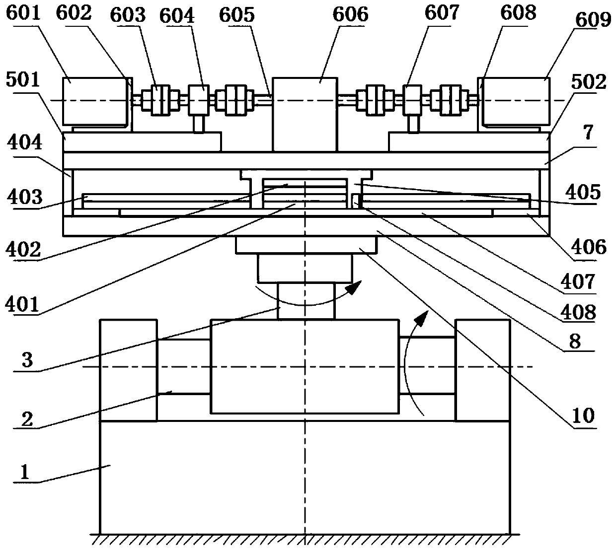
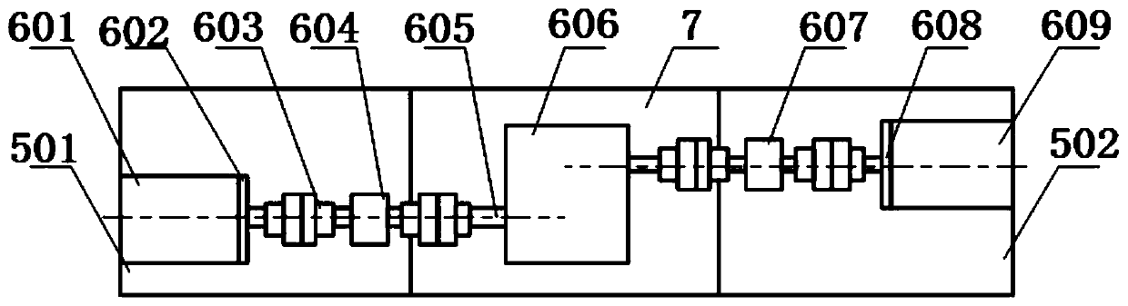
[0074] See figure 2 Or 3. The gear transmission test bench 6 includes a drive motor 601, a motor support I 602, a coupling 603, a torque speed sensor I 604, an elastic shaft 605, a gear transmission system 606, a torque speed sensor II 607, a motor support II 608 and a load motor 609 .

[0075] The driving motor 601 is mounted on a motor support I602, and the driving motor 601 transmits power to the gear transmission system 606 through two couplings 603, a torque speed sensor I604, and an elastic shaft 605.

[0076] The load motor 609 is installed on the motor support II 608, and the load motor 609 applies the load torque to the gear transmission system 606 through the two couplings 603 and the torque speed sensor II 607. T...

Embodiment 2

[0091] This embodiment discloses an experimental system capable of simulating a gear drive non-inertial system environment, including a gear drive experiment table 6, a manual cross slide group 5, a linear motion platform 4, and an electric vibration table 12.

[0092] See figure 2 Or 3. The gear transmission test bench 6 includes a drive motor 601, a motor support I 602, a coupling 603, a torque speed sensor I 604, an elastic shaft 605, a gear transmission system 606, a torque speed sensor II 607, a motor support II 608 and a load motor 609 .

[0093] The driving motor 601 is mounted on a motor support I602, and the driving motor 601 transmits power to the gear transmission system 606 through two couplings 603, a torque speed sensor I604, and an elastic shaft 605.

[0094] The load motor 609 is installed on the motor support II 608, and the load motor 609 applies the load torque to the gear transmission system 606 through the two couplings 603 and the torque speed sensor II 607. T...

Embodiment 3

[0113] The experimental method of using the experimental system described in Example 1 to simulate the non-inertial system environment of gear transmission linear acceleration includes the following steps:

[0114] 1) Connect the experimental equipment to ensure that the connection of each part is stable.

[0115] 2) Debug the gear transmission test bench 6, energize the drive motor 601, and control the gear transmission system 606 to slowly increase the speed to a certain safe speed; energize the load motor 609, and control the gear transmission system 606 to slowly load to a certain safety Load torque; confirm that the gear transmission system 606 can rotate normally, and observe whether the signal output of the torque speed sensor I604 and the torque speed sensor II607 is normal.

[0116] 3) Debug the linear motion platform 4, energize the stator part 403, the excitation magnetic field interacts with the traveling wave magnetic field to generate electromagnetic thrust, the electro...


PUM


Abstract

The invention discloses an experimental system and an experimental method capable of simulating a gear transmission non-inertial system environment, which relate to the field of aviation power transmission. The experimental system capable of simulating the gear transmission non-inertial system environment comprises a gear transmission experiment table, a linear motion platform and an electric vibration table, wherein the linear motion platform drives the gear transmission experiment table to do horizontal linear acceleration motion, so as to simulate a gear transmission linear acceleration non-inertial system environment; the electric vibration table drives the gear transmission experiment table to rotate back and forth around a horizontal shaft, so as to simulate a gear transmission pitching non-inertial system environment; and the electric vibration table drives the gear transmission experiment table to rotate back and forth around a vertical shaft, so as to simulate a gear transmission yawing non-inertial system environment. According to the experimental system and the experimental method, the dynamic experiment of a gear transmission system during basic fixation can be carriedout, the non-inertial excitation of the gear transmission system during the maneuvering flight of an aircraft can be simulated, and the vacancy of the experimental research in the aviation power transmission field considering the non-inertial system environmental conditions in China is made up.

Description

Technical field [0001] The invention relates to the field of aviation power transmission, in particular to an experimental system and method capable of simulating a gear transmission non-inertial system environment. Background technique [0002] In the non-inertial environment, the gear transmission system is excited by complex additional loads, its vibration characteristics will change, and even vibration instability will occur, which will threaten the stable operation of the aircraft. [0003] For this reason, domestic scholars have conducted a lot of research on the dynamic characteristics of the gear transmission system during maneuvering through theory and have achieved many results; however, the current domestic gear transmission system test benches do not consider the basic motion factors and cannot simulate the gear transmission system. The state of motion in a flying non-inertial system environment. [0004] In the field of aero-engine technology, the existing design simula...

Claims


Application Information

Patent Timeline
IPC IPC(8): G01M13/021G01M13/025
CPCG01M13/021G01M13/025G01M7/027Y02T90/00
Inventor 魏静姜东张爱强蒋函成
Owner CHONGQING UNIV
Why Eureka
Try Eureka