
Radar simulation method, device, storage medium and electronic equipment

A simulation method and radar technology, applied in the field of simulation, can solve the problems of simulating multiple radars, difficult to improve the simulation speed, and consumption.

Active Publication Date: 2020-02-21
万物镜像(北京)计算机系统有限公司
View PDF6 Cites 8 Cited by
  • Summary
  • Abstract
  • Description
  • Claims
  • Application Information

AI Technical Summary

Problems solved by technology

In a complex urban road simulation scene, if the above settings are followed, millions of rays per second are required to intersect with the scene, which consumes a lot of CPU
[0004] In the current mainstream algorithm for intersecting the scene by simulating each ray, there are the following problems: due to the limitation of the number of CPU cores, even if the CPU parallel mode is used, the simulation speed is difficult to improve, and the real-time simulation frame rate is not enough; One type adds a collision body that is exactly the same as the original model
For obstacles with many hollows (such as bicycles), there should be no collisions in the middle, otherwise it will affect the result of intersecting the ray and the scene, and such a simulated bicycle may include more than 100,000 vertices, and the more complex the collision body, the more complex the calculation The intersection algorithm is also more time-consuming, resulting in a significant drop in frame rate with the improvement of simulation accuracy; it is impossible to simulate multiple radars at the same time and integrate them. Currently, multiple radars are generally installed on L4 and above self-driving cars , and because each lidar consumes a large amount of CPU, it is difficult for the current mainstream simulation algorithm to simultaneously simulate multiple lidars on a single machine (single CPU)

Method used


Image

  • Radar simulation method, device, storage medium and electronic equipment
  • Radar simulation method, device, storage medium and electronic equipment
  • Radar simulation method, device, storage medium and electronic equipment

Examples


Embodiment Construction

[0074] Specific embodiments of the present disclosure will be described in detail below in conjunction with the accompanying drawings. It should be understood that the specific embodiments described here are only used to illustrate and explain the present disclosure, and are not intended to limit the present disclosure.

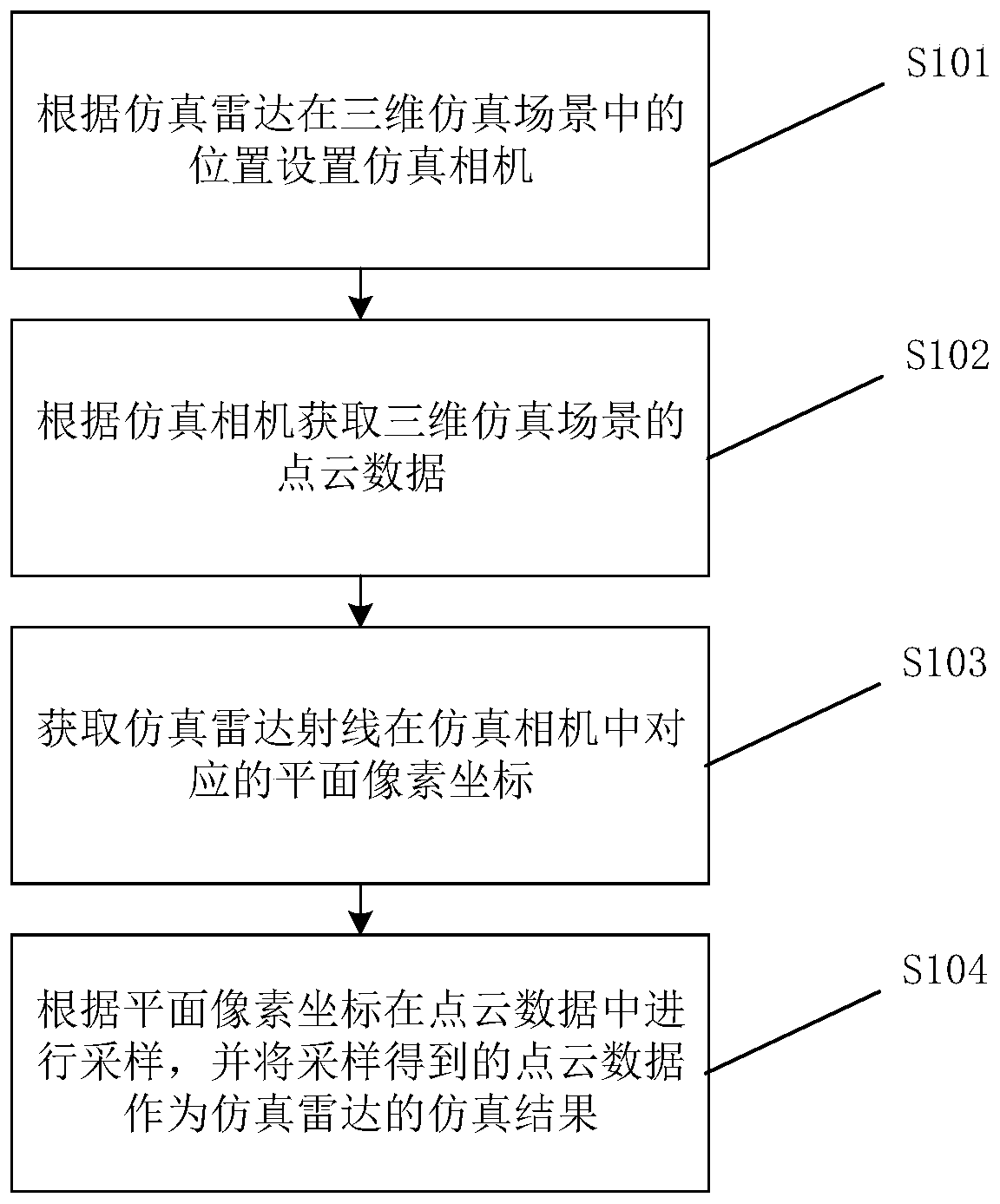
[0075] figure 1 It is a flowchart of a radar simulation method according to an exemplary embodiment of the present disclosure. Such as figure 1 As shown, according to the method, steps 101 to 104 are included.

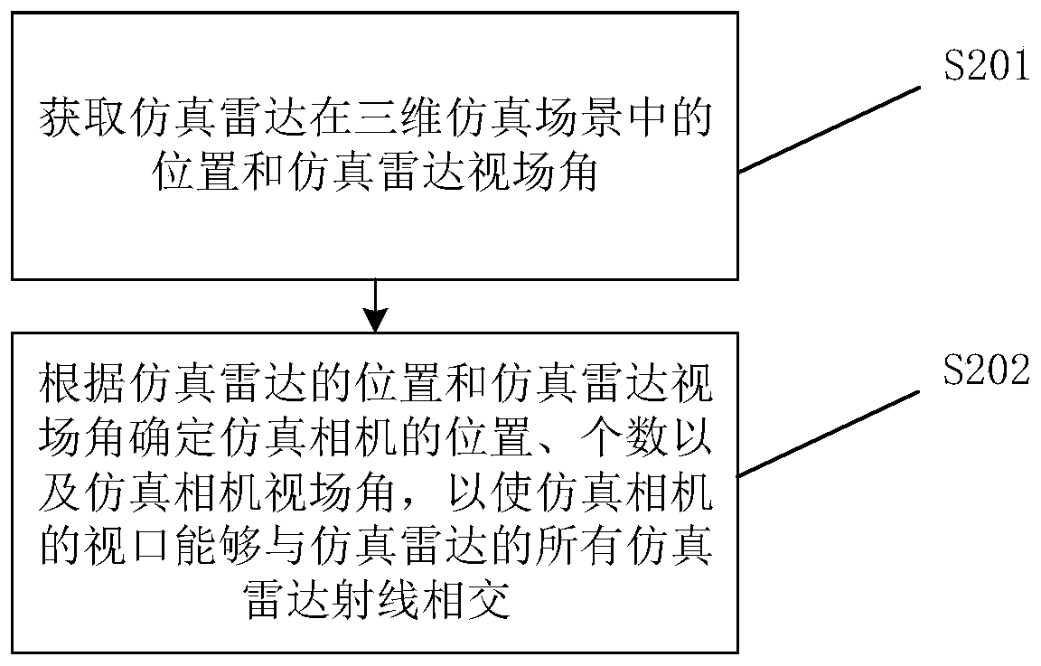
[0076] In step 101, a simulated camera is set according to the position of the simulated radar in the three-dimensional simulated scene, wherein the viewport of the simulated camera can intersect with all simulated radar rays of the simulated radar.

[0077] The three-dimensional simulation scene may be established through a high-precision map. In addition to establishing the 3D simulation scene based on high-precision map data, simulated weather,...


PUM


Abstract

The invention relates to a radar simulation method, a radar simulation device, a storage medium and electronic equipment. The method comprises the following steps that: a simulation camera is set according to the position of a simulation radar in a three-dimensional simulation scene, and the viewport of the simulation camera can intersect with all simulation radar rays of the simulation radar; thepoint cloud data of the three-dimensional simulation scene are acquired according to the simulation camera; corresponding plane pixel coordinates of the simulated radar rays in the simulated camera are acquired; and sampling is performed in the point cloud data according to the plane pixel coordinates, and point cloud data obtained by the sampling are taken as the simulation result of the simulation radar. By means of the above technical scheme, the simulation camera can be arranged to assist the simulation radar in simulation, and therefore, the simulation speed of the radar is increased toa great extent, the expansibility of the radar simulation is improved to a great extent, and multiple radars can be simulated at the same time with simulation speed guaranteed.

Description

technical field [0001] The present disclosure relates to the field of simulation, and in particular, to a radar simulation method, device, storage medium and electronic equipment. Background technique [0002] Radar simulation is to simulate the radar ray point cloud data of each frame of the actual radar according to the real radar parameters on the basis of the simulation scene. Radar simulation has the following advantages: It can save the labeling cost of real radar, because manual labeling is not only costly, but also the accuracy is worrying, and the accuracy can easily differ by more than decimeters, while the obstacle labeling of radar simulation is completely generated by the simulation scene in real time. The labeling accuracy is higher; radar simulation can simulate extreme weather and working conditions, for example, it can simulate radar point clouds in heavy rain, snow, and dense fog, and can also simulate radar point clouds in severe congestion or bad traffic ...

Claims


Application Information

Patent Timeline
IPC IPC(8): G01S7/40G06T17/10
CPCG01S7/40G06T17/10G06T2200/08
Inventor 张安春鲍世强
Owner 万物镜像(北京)计算机系统有限公司
Learn More