Method of three dimensional ray tracing in the dynamic radio wave propagation environment

a dynamic radio wave propagation and three-dimensional ray tracing technology, applied in the field of three-dimensional ray tracing for can solve the problems of path errors increasing error rate, reflection shrinkage error, and neglected existing paths, so as to enhance the accuracy of radio wave propagation prediction, improve simulation speed, and enhance the effect of simulation speed

Inactive Publication Date: 2011-06-23
ELECTRONICS & TELECOMM RES INST
View PDF8 Cites 12 Cited by
  • Summary
  • Abstract
  • Description
  • Claims
  • Application Information

AI Technical Summary

Benefits of technology

[0021]According to the present invention, a radio wave propagation environment is predicted while varying a transmission point and a receipt point, and a simulation speed is improved by an efficient simulation.
[0022]Also, when a location of a transmission point dynamically varies, a forward path from the transmission point to a receipt point is traced and then a backward path is traced. When a location of the receipt point dynamically varies, a forward path from the receipt point to the transmission point is traced and then a backward path is traced. Through the forward and backward path tracing, a reflection expansion error is removed and the accuracy of radio wave propagation prediction is increased.
[0023]Furthermore, a patch-adaptive discrete search method is used to discard a reflection shrinkage error to enhance the accuracy of radio wave propagation prediction.

Problems solved by technology

However, since the conventional ray tube tracing method is based on midpoint approximation for a path, the path is detected simply by using only a receipt point and nodes of a tree structure and thus it may occur that paths which do not exist in real are included for the calculation (reflection expansion error) or existing paths are neglected from the calculation (reflection shrinkage error).
Especially, in an indoor environment, path errors increase error rate.
In other words, a reflection shrinkage error is neglect of reflection on a part of a patch due to a midpoint of a patch which is covered and thus is not seen.
In other words, a reflection expansion error is an error which determines that reflection takes place on the whole patch due to the exposure of the midpoint of the patch, while the reflection occurs only on a part of the patch in practice.
Consequently, the simulation speed is significantly slowed down.
However, if the positions of at least one of a transmission point and a receipt point dynamically vary, the simulation time cannot be reduced with only the preprocessing.
As the result, the number of times of calculation for ray tracing will greatly increase, which will lead to a multiple increase in simulation time and a loss of simulation efficiency.

Method used


Image

  • Method of three dimensional ray tracing in the dynamic radio wave propagation environment
  • Method of three dimensional ray tracing in the dynamic radio wave propagation environment
  • Method of three dimensional ray tracing in the dynamic radio wave propagation environment

Examples


Embodiment Construction

[0036]The following detailed description is provided to assist the reader in gaining a comprehensive understanding of the methods, apparatuses and / or systems described herein. Accordingly, various changes, modifications, and equivalents of the systems, apparatuses and / or methods described herein will be suggested to those of ordinary skill in the art. Also, descriptions of well-known functions and constructions are omitted to increase clarity and conciseness.

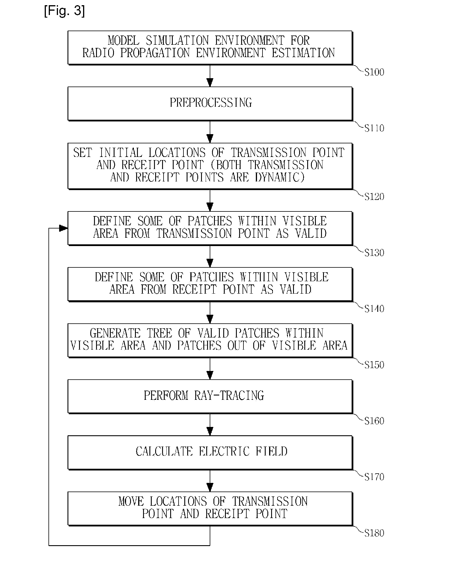
[0037]FIG. 3 is a flowchart of a ray tracing method for radio wave propagation prediction according to an exemplary embodiment.

[0038]A simulation for ray tracing is performed by an electric device such as a computer. Information required for the radio wave propagation prediction is received. Here, the information for the radio wave propagation prediction is the information on specific objects, such as buildings or terrain features which may block radio wave propagation in a particular area. Additionally, indoor obstacles for the...


PUM


Abstract

Disclosed is a three dimensional ray tracing method in a dynamic radio wave propagation environment. The method of tracing three dimensional ray in a dynamic radio wave propagation environment, by which cross tests are performed on a plurality of radio wave blocking obstacle surfaces according to a ray tube tracing scheme based on an image method in a simulation area, in which the plurality of radio wave blocking obstacle surfaces are modeled, to detect a radio path between a first point and a second point, the method comprising: defining at least a part of the radio wave blocking obstacle surfaces as valid radio wave blocking obstacle surfaces, the radio wave blocking obstacle surfaces being within a visible region from the first point of which location varies dynamically; and tracing a ray between the first point and the second point by taking into consideration only the defined valid radio wave blocking obstacle surfaces to be simulated. Accordingly, even when both locations of a transmission point and a receipt point vary, a three dimensional ray tracing for radio wave propagation prediction is possible and simulation efficiency can be maintained.

Description

TECHNICAL FIELD[0001]The present invention relates to three dimensional ray tracing for radio wave propagation prediction, and more particularly, to ray tracing by use of a ray tube based on an image method.BACKGROUND ART[0002]The importance of radio wave propagation prediction has been increasingly emphasized particularly in a city area which has an amount of radio wave blocking obstacles. A ray tube tracing method based on an image method is one of methods for radio wave propagation prediction. The image method obtains image points on all surfaces of each of radio wave blocking obstacles (e.g. buildings, radio wave scattering terrain features, etc.), which may reflect rays radiated from a transmission point, receives a signal from each image point, and calculates the received signal using a receipt point to measure a received power. By combining the image method with a ray tube scheme, a ray tube tracing method based on an image method is obtained to measure a received power of a ...

Claims


Application Information

Patent Timeline
Patent Type & Authority Applications(United States)
IPC IPC(8): G06G7/48
CPCH04W16/22G06G7/48H04B10/00H04B17/00
Inventor YOON, YOUNG-KEUNHONG, HEON-JIN
Owner ELECTRONICS & TELECOMM RES INST
Why Eureka
Try Eureka