Battery and battery manufacturing method

A battery and cell technology, applied to small-sized batteries/battery packs, large-sized batteries/battery packs, secondary batteries, etc. The negative electrode sheet can not be fully protected and other problems, so as to improve the effect of easy falling off and not easy to break

Pending Publication Date: 2020-02-21
ZHUHAI GUSHINE ELECTRONICS TECH CO LTD
View PDF0 Cites 0 Cited by
  • Summary
  • Abstract
  • Description
  • Claims
  • Application Information

AI Technical Summary

Problems solved by technology

[0002] In the production process of polymer batteries in the past, multi-layer materials are usually used to wind up the winding body, and then the winding body is wrapped by the sealing edge, and the tabs of the positive and negative electrodes are connected to the sealing edge. When external impact occurs, the positive and negative poles on the sealing edge are prone to breakage
[0003] For this reason, the prior art proposes a battery, which integrates the PCB board of the battery and the battery cell assembly, wraps it in an all-round way with an injection molding layer and leads out the connecting wires. Due to the obstruction of the PCB board, the plastic cannot be fully filled during the injection molding process. If the gaps are filled, the positive and negative plates cannot be fully protected, and the positive and negative plates are still easy to fall off when impacted by external force.

Method used


Image

  • Battery and battery manufacturing method
  • Battery and battery manufacturing method
  • Battery and battery manufacturing method

Examples


Embodiment Construction

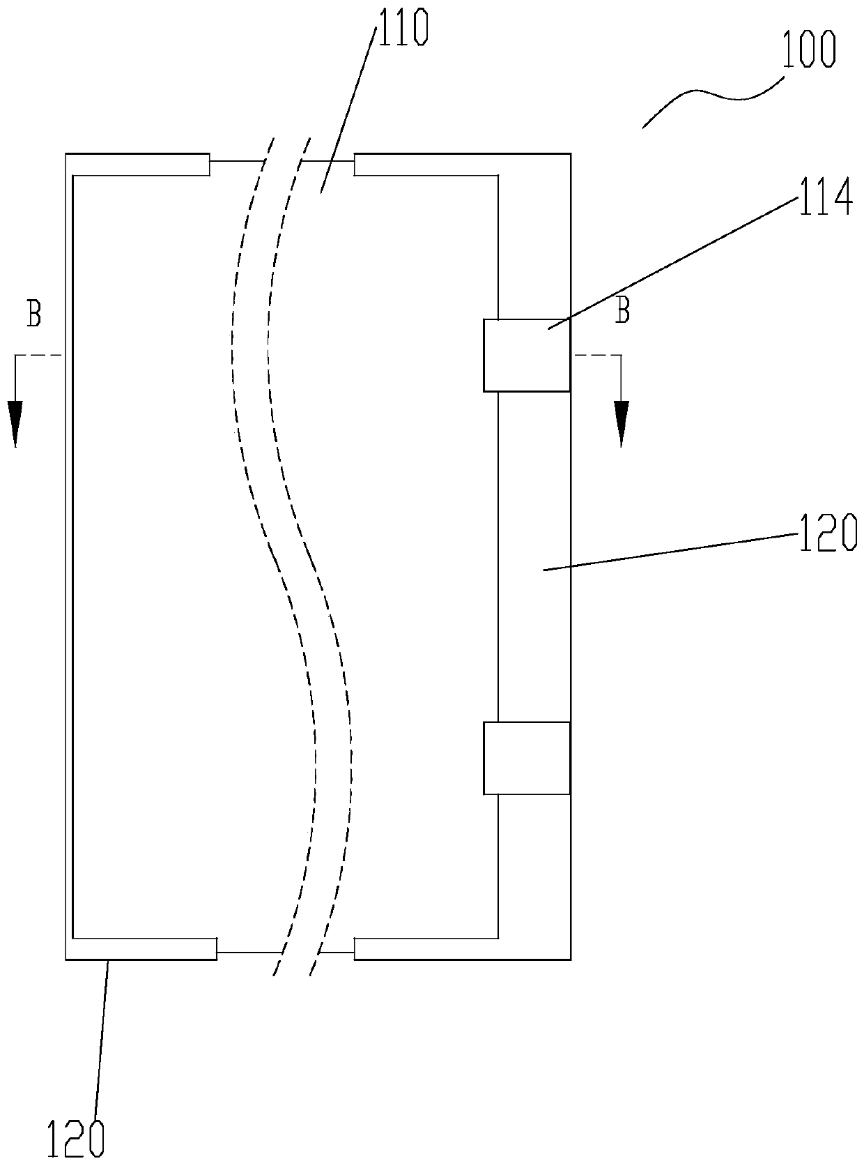
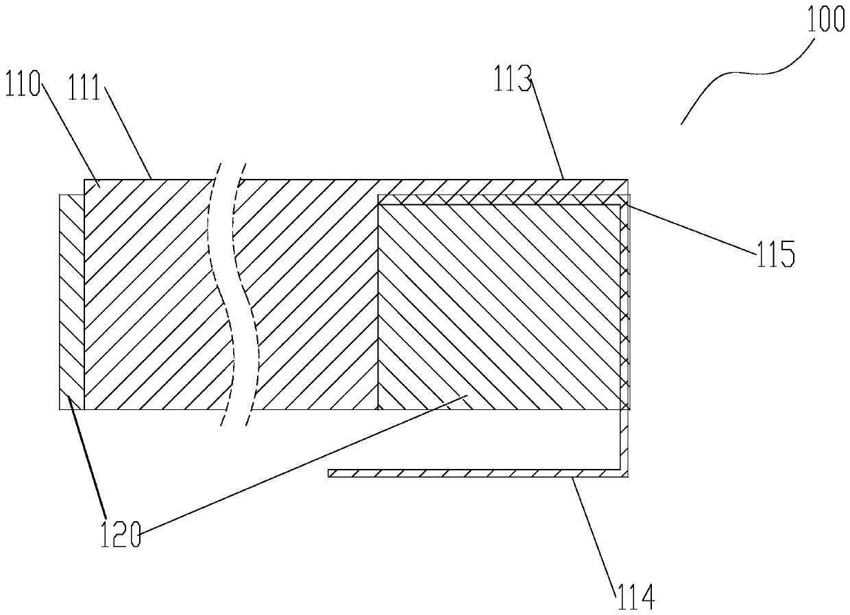
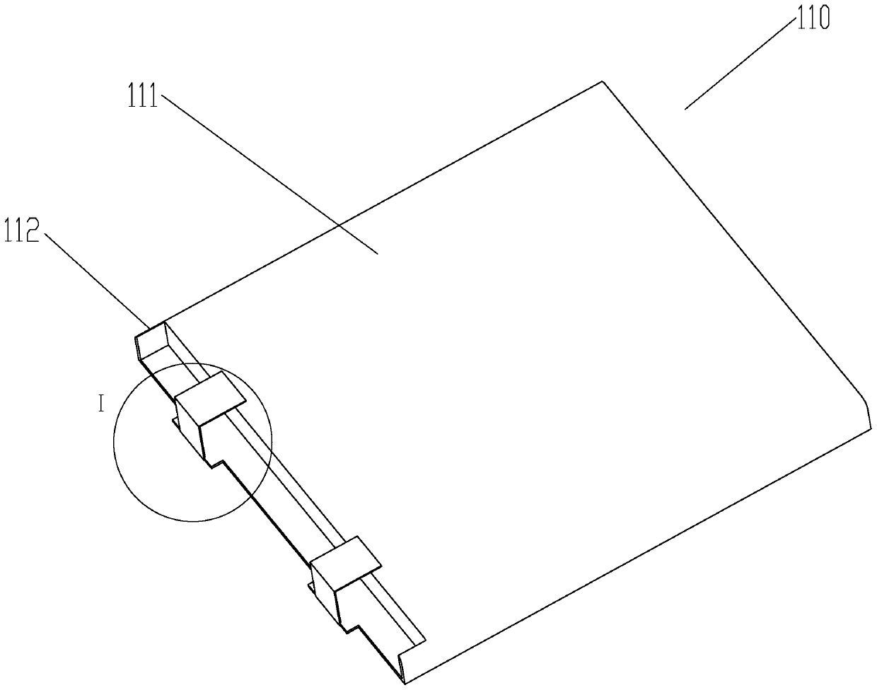
[0026] The embodiments of the present invention are described in detail below. Examples of the embodiments are shown in the accompanying drawings, wherein the same or similar reference numerals represent the same or similar elements or elements with the same or similar functions. The embodiments described below with reference to the drawings are exemplary, and are only used to explain the present invention, but should not be understood as limiting the present invention.

[0027] In the description of the present invention, it should be understood that the orientation description involved, such as up, down, front, back, left, right, etc., indicates the orientation or positional relationship based on the orientation or positional relationship shown in the drawings, and only In order to facilitate the description of the present invention and simplify the description, it does not indicate or imply that the pointed device or element must have a specific orientation, be configured and o...


PUM

PropertyMeasurementUnit
Thicknessaaaaaaaaaa

Abstract

The invention discloses a battery which comprises a battery cell assembly and a shell. The battery cell assembly comprises a battery cell body and a buffer structure. The battery cell body comprises abattery cell winding body and a tab, and the tab and the battery cell winding body are electrically connected. The tab is connected with a pole piece, and the buffer structure wraps the joint of thepole piece and the tab. The battery cell assembly is positioned in the shell. By applying the battery provided by the invention, the situation in which the pole piece is easy to fall off when the battery is impacted can be improved. The invention also provides a battery manufacturing method.

Description

Technical field [0001] The present invention relates to the field of batteries, in particular to a battery and a battery manufacturing method. Background technique [0002] In the past production process of polymer batteries, multi-layer materials are usually used to wind the wound body, and then the wound body is wrapped by the sealing edge, and the tabs of the positive and negative electrodes are connected to the sealing edge. When an external impact occurs, the positive and negative electrodes on the sealing edge are prone to breakage. [0003] For this reason, the prior art proposes a battery that integrates the PCB board of the battery with the battery cell assembly, wraps it with an injection molding layer in all directions, and draws out the connecting wire. Due to the block of the PCB board, the plastic cannot be fully filled in the injection molding process. All the gaps are full, so that the positive and negative plates cannot be fully protected, and the positive and neg...

Claims


Application Information

Patent Timeline
IPC IPC(8): H01M2/02H01M2/10H01M2/26H01M10/0587
CPCH01M10/0587H01M50/10H01M50/20H01M50/531Y02E60/10Y02P70/50
Inventor 陈赵云孟辉黄伟金
Owner ZHUHAI GUSHINE ELECTRONICS TECH CO LTD
Why Eureka
Try Eureka