Communication combiner automatic debugging system

An automatic debugging and combiner technology, which is applied in the field of communication combiners to achieve the effects of improving stability, improving debugging accuracy and improving service life

Active Publication Date: 2020-04-14
CHENGDU TIANDA INSTR EQUIP CO LTD
View PDF9 Cites 0 Cited by
  • Summary
  • Abstract
  • Description
  • Claims
  • Application Information

AI Technical Summary

Problems solved by technology

[0007] The purpose of the present invention is to provide an automatic debugging system for a communication combiner, which solves the needs of the existing communication combiner for a debugging system with high precision of debugging results, simple operation of the debugging system, and convenient later maintenance

Method used


Image

  • Communication combiner automatic debugging system
  • Communication combiner automatic debugging system
  • Communication combiner automatic debugging system

Examples


Embodiment 1

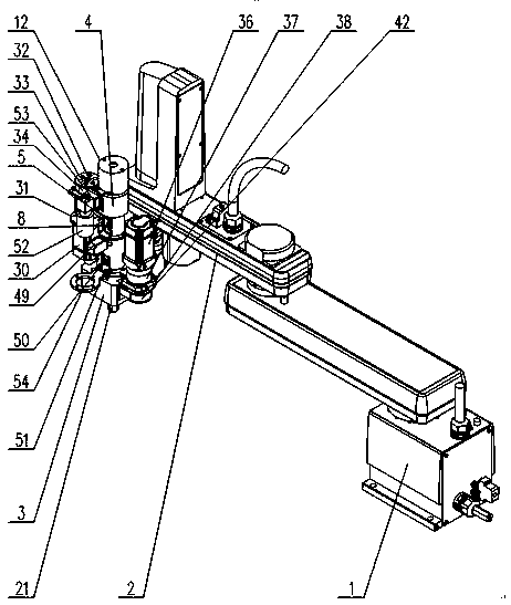
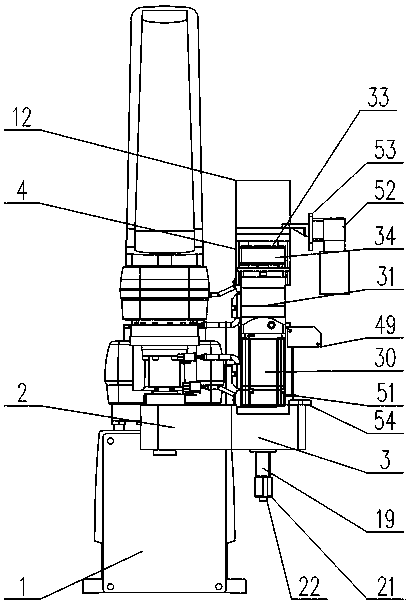
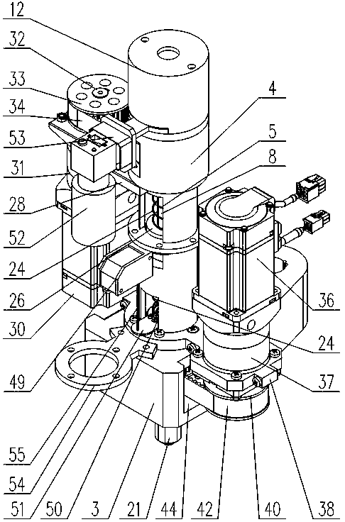
[0054] Such as Figure 1-Figure 15 As shown, the communication combiner automatic debugging system includes a robot 1 and a debugging device fixed on the control end of its mechanical arm 2. The debugging device includes a bracket, which rotates the screw adjustment assembly arranged on the bracket and driven by the first drive assembly to rotate. The nut adjustment assembly is set on the bracket, sleeved on the screw adjustment assembly, and driven by the second drive assembly. The first drive assembly is fixed on one side of the bracket, and its output shaft is located at the top, and through the reversing A transmission mechanism is used to drive the screw adjustment assembly to rotate, and the first drive assembly and the second drive assembly are alternately distributed in the circumferential direction of the screw adjustment assembly.

[0055] The reversing transmission mechanism can adopt a synchronous belt transmission mechanism, a bevel gear transmission mechanism, a ...

Embodiment 2

[0058] This embodiment is based on Embodiment 1, and describes the specific implementation structure of the bracket.

[0059] In the present invention, if image 3 with Figure 4 As shown, the support includes a base 3 fixed on one side of the manipulator 2 control end and a column 4 vertically fixed on the upper surface of the base 3, the column 4 is preferably fixed on the free end of the base 3, and the peripheral wall of the column 4 The bottom side of the bottom side protrudes outward into a flange, and the bolt is threaded with the base 3 after passing through the flange, so that the column 4 is detachably fixed on the base 3; the column 4 is provided with a through hole A6, and the through hole A6 The axis coincides with the axis of the column 4; the base 3 is provided with a through hole B7 coincident with the axis of the through hole A6;

[0060] Both the screw adjustment assembly and the nut adjustment assembly are rotatably fixed in the through hole A6, and their ...

Embodiment 3

[0063] This embodiment is based on the second embodiment, and describes the specific implementation of the screw adjustment assembly and the nut adjustment assembly.

[0064] The screw adjustment assembly includes a spline shaft A8 whose axes coincide with each other, a spline shaft sleeve A9, a coupling 10, a screwdriver rod 11 and a return spring, and the spline shaft sleeve A9 is sleeved on the spline shaft A8 , and is fixed in the through hole A6 by bearing rotation; the bottom end of the spline shaft A8 passes through the spline sleeve A9 and is connected with the top of the screwdriver rod 11 through the coupling 10, and the screwdriver rod 11 The bottom end is the bit, which is the adjustment end of the screw adjustment assembly, and it passes through the through hole B7; the return spring is sleeved on the spline shaft A8, and the screwdriver rod 11 moves upward relative to the spline shaft sleeve A9 , the return spring is in a compressed state.

[0065] The nut adjus...


PUM


Abstract

The invention discloses an automatic debugging system for a communication combiner. The automatic debugging system comprises a robot and a debugging device fixed on the mechanical arm control end of the robot. The debugging device comprises a bracket, a screw rod adjusting assembly which is rotationally arranged on the bracket and rotationally driven by a first driving assembly, and a nut adjusting assembly which is is rotationally arranged on the bracket, arranged on the screw rod adjusting assembly in a sleeving mode and driven by a second driving assembly in a rotating mode. The first driving assembly is fixed on one side of the bracket, and an output shaft of the first driving assembly is located at the top end. The screw rod adjusting assembly is driven to rotate through a reversing transmission mechanism. According to the invention, the axial size of the device is reduced; the height position of the first driving assembly is lowered; and the whole gravity center of the device moves downwards, which reduces the shaking amplitude of the device, improves the stability of the mechanism, reduces the influence of vibration generated in the working process of a motor on the debugging precision, improves the mechanical property of the debugging device in the working process, and prolongs the service lives of main components.

Description

technical field [0001] The invention relates to the field of communication combiners, in particular to an automatic debugging system for communication combiners. Background technique [0002] In each debugging of the communication combiner, the adjustment process of each tuning screw and coupling screw must first loosen the lock nut, then turn the tuning screw or coupling screw to adjust the length of the tuning screw or coupling screw, and then tighten Lock nut process. Since each debugging needs to be repeated many times, when manual debugging is used, the debugging results will be deviated due to human factors, resulting in poor consistency of the same batch of factory communication combiners; at the same time, the manual debugging speed is slow, which is not conducive to mass production. [0003] At the same time, the prior art CN208336468U discloses a fine-tuning device for adjusting the tuning screw and the lock nut, which includes a bracket, a screw adjustment assemb...

Claims


Application Information

Patent Timeline
Patent Type & Authority Patents(China)
IPC IPC(8): H01P1/20H01P11/00
CPCH01P1/20H01P11/00H01P11/007
Inventor 郑兆祥
Owner CHENGDU TIANDA INSTR EQUIP CO LTD
Why Eureka
Try Eureka