Power electrical power distribution cabinet for photovoltaic power station

A photovoltaic power station, electric power technology, applied in the substation/power distribution device casing, substation, substation/switchgear cooling/ventilation, etc., can solve the problem that the heat of the electrical cabinet is difficult to dissipate, affecting the use efficiency of the power distribution cabinet, distribution The problem of large floor space of the electric cabinet can achieve the effect of increasing heat transfer efficiency, lowering temperature and reducing floor space

Inactive Publication Date: 2020-02-21
莫庆锋
View PDF9 Cites 4 Cited by
  • Summary
  • Abstract
  • Description
  • Claims
  • Application Information

AI Technical Summary

Problems solved by technology

[0005] The invention provides a power distribution cabinet for a photovoltaic power station, which is not affected by sunlight and the temperature of the external airflow, has good heat dissipation effect, reduces the investment of heat dissipation equipment, does not occupy the surface area, and improves the utilization rate of the land. The advantage of solving the problem is that in order to ensure sufficient solar energy, photovoltaic power stations are usually selected in areas with a large amount of sunlight, resulting in high surface temperature in this area, and the existing power distribution cabinets are installed on the ground As a result, the power distribution cabinet is exposed to sunlight for a long time, and the temperature of the case is high, which interacts with the heat generated by the internal electrical components, causing the internal temperature of the power distribution cabinet to rise sharply. High temperature The air temperature in this area is also high, which makes it difficult to dissipate the heat inside the electrical cabinet, which seriously affects the use efficiency of the power distribution cabinet, and the power distribution cabinet installed on the ground occupies a large area, reducing problem of land use

Method used


Image

  • Power electrical power distribution cabinet for photovoltaic power station
  • Power electrical power distribution cabinet for photovoltaic power station
  • Power electrical power distribution cabinet for photovoltaic power station

Examples


Embodiment Construction

[0022] The following will clearly and completely describe the technical solutions in the embodiments of the present invention with reference to the accompanying drawings in the embodiments of the present invention. Obviously, the described embodiments are only some, not all, embodiments of the present invention. Based on the embodiments of the present invention, all other embodiments obtained by persons of ordinary skill in the art without making creative efforts belong to the protection scope of the present invention.

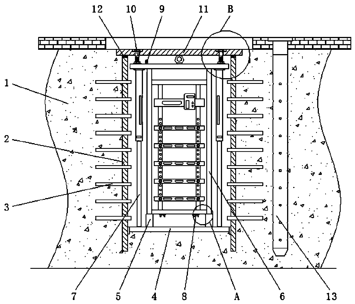
[0023] see Figure 1-3 , a power distribution cabinet for a photovoltaic power station, comprising a ground soil layer 1, a sealing baffle 2 is arranged inside the ground soil layer 1, and a heat dissipation conduit 3 is fixedly installed on the outer surface of the sealing baffle 2, and the heat dissipation conduit One end of the 3 extends to the inside of the ground soil layer 1, and the other end of the heat dissipation conduit 3 extends to the inner cavity...


PUM


Abstract

The invention relates to the technical field of photovoltaic power generation equipment, and further discloses a power electrical power distribution cabinet for a photovoltaic power station; a groundsoil layer is included, and a sealing baffle is arranged in the ground soil layer; a heat dissipation guide pipe is fixedly installed on the outer surface of the sealing baffle, a supporting bottom plate is fixedly installed at the bottom of an inner cavity of the sealing baffle, a power distribution cabinet frame is movably sleeved with a fixing sleeve, and the four corners of the top end of thepower distribution cabinet frame are fixedly connected with the top end of the supporting bottom plate through four sets of lifting mechanisms correspondingly. The invention discloses the power electrical power distribution cabinet for the photovoltaic power station. The power distribution cabinet is installed in a buried manner, so the buried mode power distribution cabinet can effectively avoidthe influence of sunlight irradiation or high-temperature airflow of external temperature on the power distribution cabinet in an environment with large sunshine amount, such that the influence of theexternal temperature on the power distribution cabinet is reduced, the occupied space of the power distribution cabinet can be greatly reduced by adopting the buried mode power distribution cabinet,and the utilization rate of land is increased.

Description

technical field [0001] The invention relates to the technical field of photovoltaic power generation equipment, in particular to a power distribution cabinet for a photovoltaic power station. Background technique [0002] The electric power distribution cabinet is an effective management device that centrally sets the switchgear, electrical components, measuring instruments, protection and auxiliary electrical appliances, and forms an orderly operation. It is widely used because of its characteristics of limited, stable and reliable operation and high space utilization. [0003] Among them, photovoltaic power stations, as an efficient, stable and sustainable place to generate electricity using solar energy, are also inevitable for the use of power and electrical distribution cabinets. However, in order to ensure sufficient solar energy, photovoltaic power stations usually choose to The area with a large amount of sunlight leads to a higher surface temperature in this area, ...

Claims


Application Information

Patent Timeline
Patent Type & Authority Applications(China)
IPC IPC(8): H02B1/30H02B1/56H02B7/08
CPCH02B1/30H02B1/565H02B7/08
Inventor 莫庆锋
Owner 莫庆锋
Why Eureka
Try Eureka