Underwater cable protection device

A protection device, underwater cable technology, applied in the direction of electrical components, etc., can solve the problems of underwater cable damage, impact of underwater cable service life, underwater cable bending, etc., to achieve the effect of ensuring stability

Pending Publication Date: 2020-02-21
宁波泛叶海洋科技有限公司
View PDF0 Cites 0 Cited by
  • Summary
  • Abstract
  • Description
  • Claims
  • Application Information

AI Technical Summary

Problems solved by technology

In the above structure, since the underwater cable is mainly supported by the tower wall, the underwater cable will move under the influence of tides and bad weather. friction, so that the outer wall of the underwater cable is damaged, especially the edge of the installation hole is easy to cause the underwater cable to bend, which will cause damage to the underwater cable, affect the service life of the underwater cable, and then affect the offshore power generation system normal operation

Method used


Image

  • Underwater cable protection device
  • Underwater cable protection device
  • Underwater cable protection device

Examples


Embodiment 1

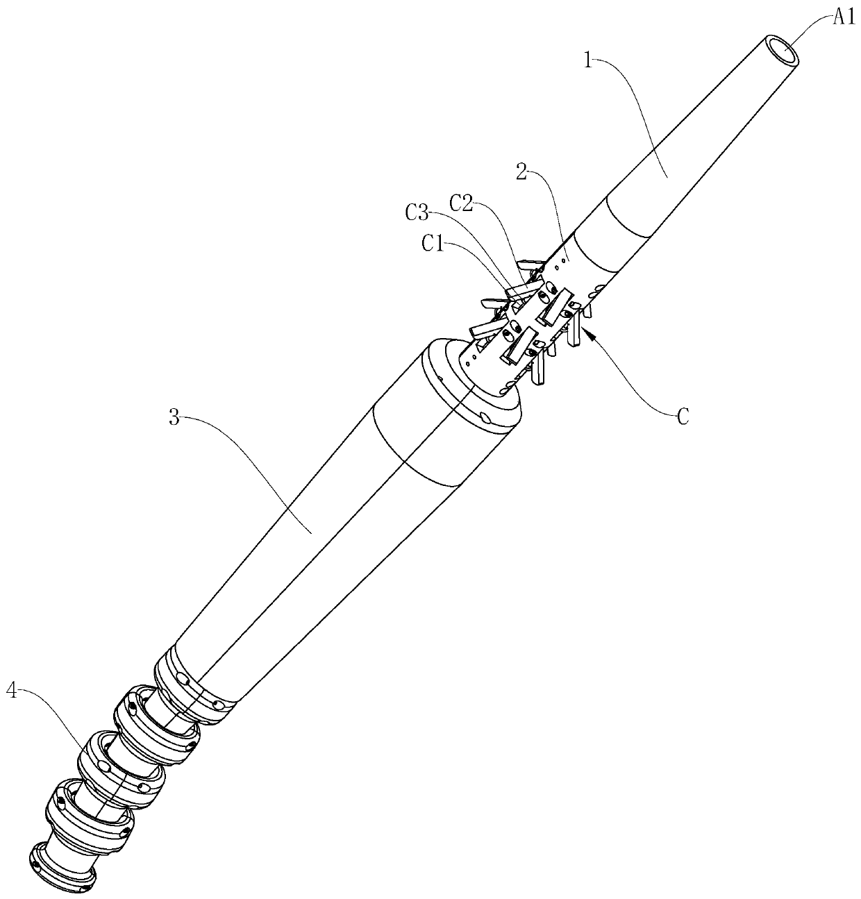
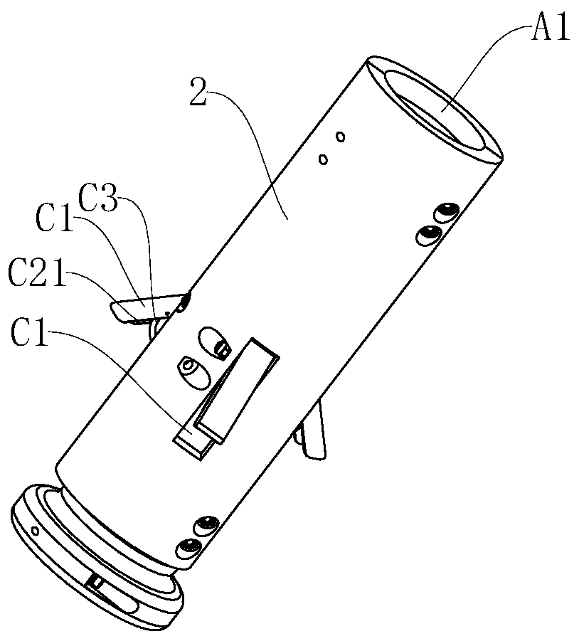
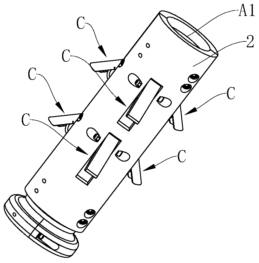
[0045] Embodiment 1: As shown in the figure, an underwater cable protection device includes a protection device body provided with a central through hole A1 for the underwater cable A to pass through the installation. The protection device body includes flexible guides connected sequentially from top to bottom. Tube 1, rigid positioning tube 2 and flexible anti-bending tube 3, the flexible guide tube 1 is a tapered tube with gradually larger outer diameter from top to bottom, and the maximum outer diameter of the flexible guide tube 1 is smaller than the water supply bottom set on the wall of the tower B. The inner diameter of the installation hole B1 where the cable A passes through the installation, the rigid positioning tube 2 is a cylindrical tube with the same outer diameter everywhere, the outer diameter of the rigid positioning tube 2 is equal to the maximum outer diameter of the flexible guiding tube 1, and the flexible guiding tube 1 The anti-bending pipe 3 is a tapere...

Embodiment 2

[0051] Embodiment 2: Other parts are the same as Embodiment 1, the difference is that the elastic support member C3 is a spring, one end of the spring is fixedly installed on the inner end surface of the rigid positioning block C2, and the other end of the spring is fixedly installed on the bottom of the groove C1 end face.

Embodiment 3

[0052] Embodiment 3: other parts are the same as Embodiment 1 or Embodiment 2, the difference is that the positioning mechanism includes multiple sets of positioning components, and multiple sets of positioning components are arranged at intervals up and down.

[0053] In this particular embodiment, there are 2 groups of positioning components.


PUM


Abstract

The invention discloses an underwater cable protection device, which is characterized by comprising a protection device body, wherein the protection device body comprises a flexible guide pipe, a rigid positioning pipe and a flexible anti-bending pipe which are sequentially connected from top to bottom, the flexible guide pipe is a conical pipe with the outer diameter being gradually increased from top to bottom, the maximum outer diameter of the flexible guide pipe is less than the inner diameter of a mounting hole which is formed in the wall of a tower drum and used for mounting an underwater cable in a penetrating mode, the rigid positioning pipe is a cylindrical pipe with the same outer diameter at each part, the outer diameter of the rigid positioning pipe is equal to the maximum outer diameter of the flexible guide pipe, the flexible anti-bending pipe is a conical pipe with the outer diameter being gradually decreased from top to bottom, the maximum outer diameter of the flexibleanti-bending pipe is greater than the inner diameter of the mounting hole, the rigid positioning pipe is provided with a positioning mechanism, the flexible guide pipe is arranged in the tower drum after the mounting is completed, the rigid positioning pipe is mounted in the mounting hole, and the flexible anti-bending pipe is located outside the tower drum. The underwater cable protection devicehas the advantages that the structure is simple, the underwater cable is effectively protected, and the service life of the underwater cable is ensured.

Description

technical field [0001] The invention relates to the field of marine engineering, in particular to an underwater cable protection device. Background technique [0002] As my country's demand for energy continues to increase, the development of marine renewable energy such as offshore wind power is also being strengthened. more and more widely applied. The electricity generated by offshore wind power mainly comes from the generators driven by the turbines on the wind turbines, and one or more generators are connected together by submarine cables, and the power is transmitted to the shore through submarine cables. [0003] At present, for the offshore wind power generation system of the single-pile tower type, one end of the underwater cable used for power transmission is used to connect the generator in the tower. The tower is usually embedded in the seabed. The hole is used for the penetration of the underwater cable to provide a certain support for the underwater cable. In...

Claims


Application Information

Patent Timeline
IPC IPC(8): H02G9/00
CPCH02G9/00
Inventor 钟科星
Owner 宁波泛叶海洋科技有限公司
Why Eureka
Try Eureka