
Series-parallel magnetic circuit hybrid magnetic pole type memory motor

A technology of mixed magnetic poles and memory motors, which is applied in the direction of magnetic circuits, magnetic circuit static parts, magnetic circuit rotating parts, etc., can solve problems such as space congestion and reduce design difficulty, so as to solve the problem of overcrowded space, reduce design difficulty, The effect of improving stability

Inactive Publication Date: 2020-02-21
SOUTHEAST UNIV
View PDF5 Cites 3 Cited by
  • Summary
  • Abstract
  • Description
  • Claims
  • Application Information

AI Technical Summary

Problems solved by technology

[0006] Purpose of the invention: The present invention provides a series-parallel magnetic circuit hybrid magnetic pole type memory motor for the respective shortcomings of the current traditional series or parallel magnetic circuit hybrid permanent magnet memory motor, which better integrates and inherits the two magnetic circuit hybrid permanent magnet memory motors Respective advantages, broaden the range of motor magnetic adjustment, and at the same time ensure the stability of the permanent magnet operating point
In addition, the arrangement of mixed magnetic poles can solve the problem of overcrowded space under the same magnetic pole and reduce the difficulty of design

Method used


Image

  • Series-parallel magnetic circuit hybrid magnetic pole type memory motor
  • Series-parallel magnetic circuit hybrid magnetic pole type memory motor
  • Series-parallel magnetic circuit hybrid magnetic pole type memory motor

Examples


Embodiment Construction

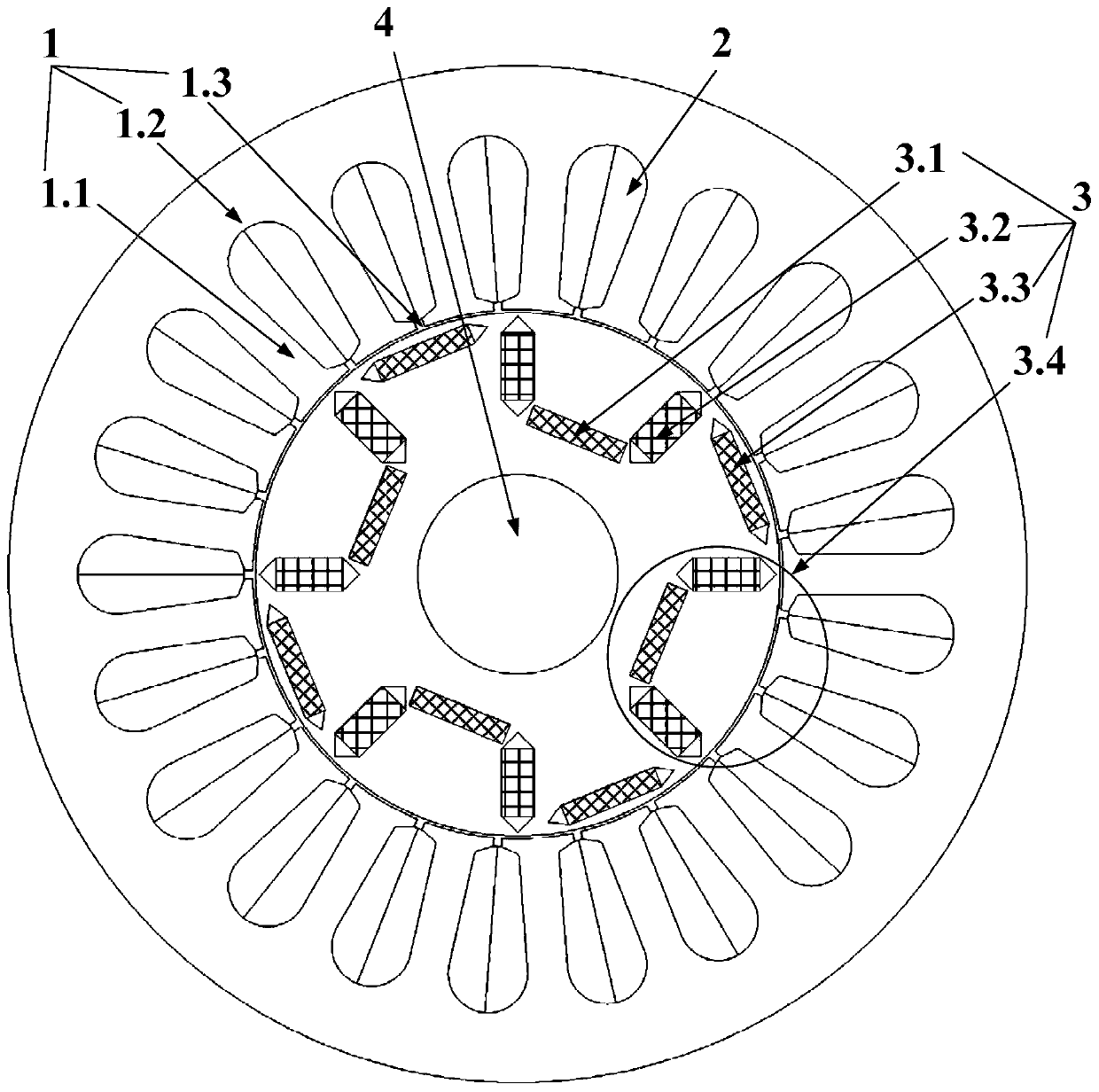
[0016] Please combine figure 1 As shown, the series-parallel magnetic circuit hybrid pole memory motor involved in this example includes a stator 1 , an armature winding 2 , a hybrid permanent magnet rotor 3 and a rotating shaft 4 . The rotating shaft 4, the hybrid permanent magnet rotor 3 and the stator 1 are arranged sequentially from inside to outside. The stator 1 includes stator core teeth 1.1 and stator yoke 1.2, the stator core teeth 1.1 are arranged between the stator yoke 1.2 and the hybrid permanent magnet rotor 3, and a cavity 1.3 is formed between adjacent stator core teeth 1.1, which is used to place windings on the stator core The three-phase armature winding 2 on the teeth 1.1 and the hybrid permanent magnet rotor 3 are arranged around the outside of the rotating shaft 4 . The rotor core of the hybrid permanent magnet rotor 3 adopts a hybrid magnetic pole structure with multiple pairs of magnetic poles, and two adjacent magnetic poles adopt different permanent ...


PUM


Abstract

The invention discloses a series-parallel magnetic circuit hybrid magnetic pole type memory motor, which comprises a stator, an armature winding, a hybrid permanent magnet rotor, and a rotating shaft.The armature winding is arranged on the stator. The hybrid permanent magnet rotor is arranged on the inner side of the stator. The rotating shaft is arranged on the inner side of the hybrid permanentmagnet rotor. A plurality of pairs of magnetic poles are arranged on a rotor core of the hybrid permanent magnet rotor. A U-shaped permanent magnet structure composed of a first permanent magnet magnetized in the radial direction and two adjacent second permanent magnets magnetized in the tangential direction is arranged at the N pole of each pair of magnetic poles, and a third permanent magnet magnetized in the radial direction is arranged at the S pole. The first permanent magnets are placed close to the rotating shaft, and the third permanent magnets are placed close to the air gap side. The coercive force of each first permanent magnet and the coercive force of each third permanent magnet are larger than the coercive force of each second permanent magnet. The magnetic regulation rangeof the motor can be broadened, and the stability of the permanent magnet working point can be ensured.

Description

technical field [0001] The invention relates to a memory motor, in particular to a series-parallel magnetic circuit mixed magnetic pole type memory motor. Background technique [0002] Permanent magnet synchronous motor (Permanent Magnet Synchronous Machine, PMSM) has the advantages of high power density, high efficiency, reliable operation and strong overload capacity due to the use of traditional rare earth permanent magnet materials with high magnetic energy product (such as NdFeB). An important direction for the development of the discipline. Due to the inherent characteristics of ordinary permanent magnet materials (such as NdFeB), the air gap magnetic field in the traditional permanent magnet synchronous motor is basically kept constant, and the speed regulation range is very limited when it is operated as an electric motor. Therefore, the adjustable flux permanent magnet motor aiming at realizing the effective adjustment of the air gap magnetic field of the permanent...

Claims


Application Information

Patent Timeline
Patent Type & Authority Applications(China)
IPC IPC(8): H02K1/27H02K1/12
CPCH02K1/12H02K1/276
Inventor 阳辉郑昊林鹤云
Owner SOUTHEAST UNIV
Learn More