Motor power-off brake system and method

A motor and brake technology, applied in the field of motor power-off brake system, can solve the problems of reducing the service life of circuit components, motor coil winding damage, coil winding short circuit, etc., and achieve the effect of reducing interference

A motor and brake technology, applied in the field of motor power-off brake system, can solve the problems of reducing the service life of circuit components, motor coil winding damage, coil winding short circuit, etc., and achieve the effect of reducing interference

CN110829951AInactive Publication Date: 2020-02-21SUNONWEALTH ELECTRIC MACHINE IND

Image

  • Motor power-off brake system and method
  • Motor power-off brake system and method
  • Motor power-off brake system and method

Examples


Embodiment Construction

[0040] In order to make the above-mentioned and other objects, features and advantages of the present invention more obvious and understandable, the preferred embodiments of the present invention are listed below, together with the accompanying drawings, and are described in detail as follows:

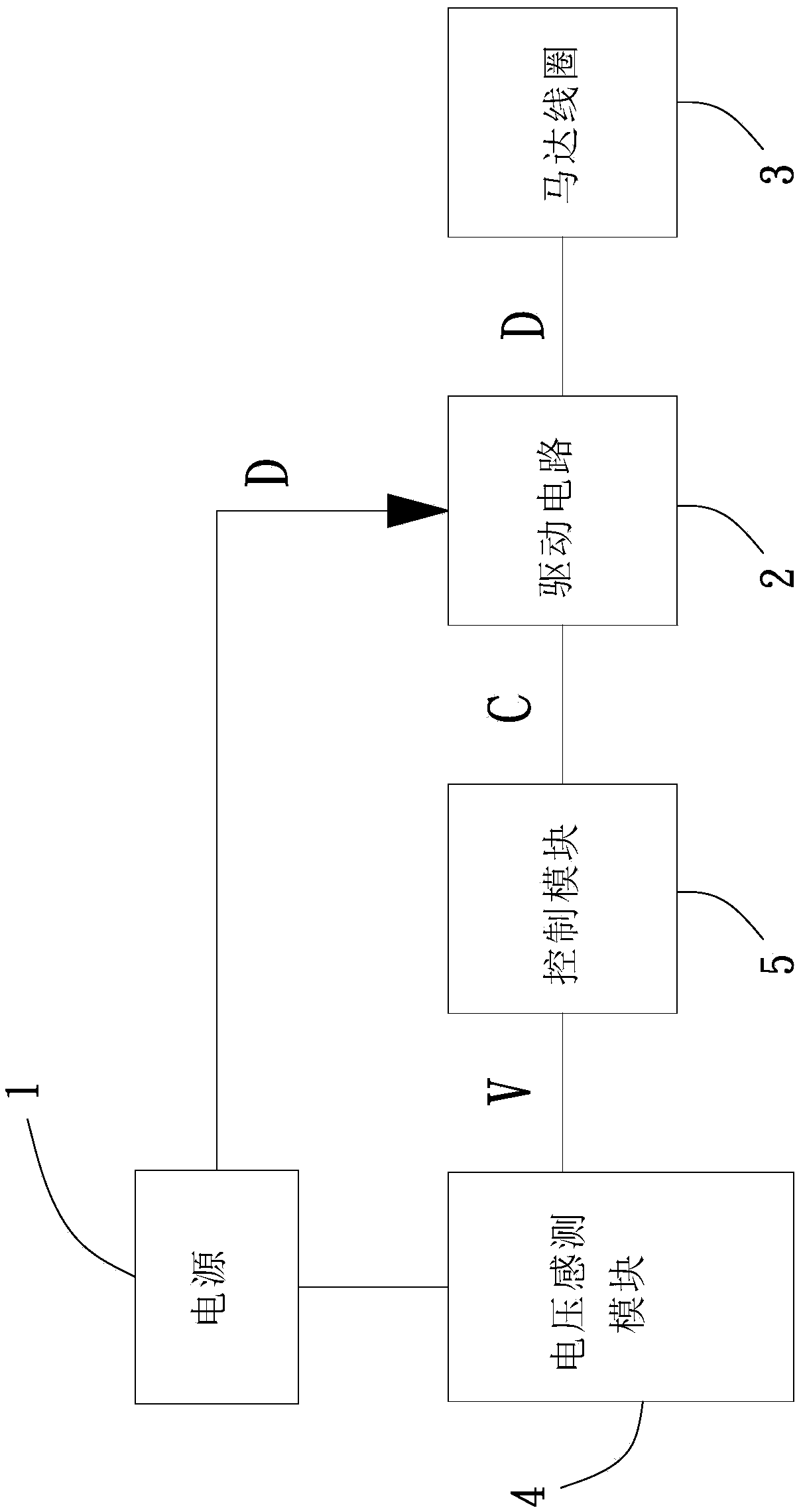
[0041] Please refer to figure 1 As shown, it is a preferred embodiment of the motor power-off braking system of the present invention, including a power supply 1, a drive circuit 2, a motor coil 3, a voltage sensing module 4 and a control module 5, the power supply 1 The drive circuit 2 is electrically connected to the voltage sensing module 4, the drive circuit 2 is electrically connected to the motor coil 3, and the control module 5 is electrically connected to the drive circuit 2 and the voltage sensing module 4 respectively. .

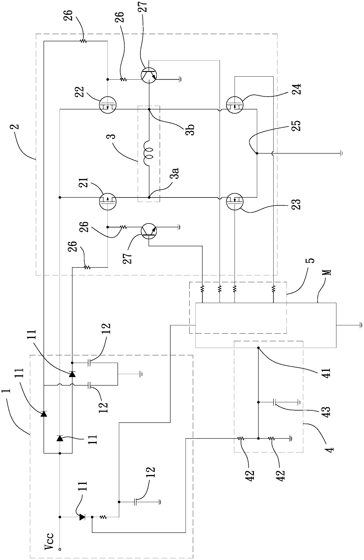
[0042] Please refer to figure 2 As shown, the power supply 1 includes a DC power supply source Vcc, the power supply 1 may also include a plurality of r...


PUM


Abstract

A motor power-off brake system and method are used for solving the problem that surge is caused by switching operation of an existing motor power-off brake to damage a motor coil winding. The brake system comprises a power supply; a driving circuit electrically connected with the power supply; a motor coil electrically connected with the driving circuit; a voltage sensing module electrically connected with the power supply and used for measuring the voltage of the power supply and generating a monitoring voltage value; and a control module electrically connected with the driving circuit and the voltage sensing module and used for receiving the monitoring voltage value. The control module judges that the power supply is about to be powered off according to the monitoring voltage value, a control signal is generated through the control module, the driving circuit and the motor coil are switched to form an open circuit and the open circuit is maintained for a period of time, and the driving circuit and the motor coil are switched to form a closed loop.

Description

technical field [0001] The invention relates to a method for protecting a power system, in particular to a motor power-off braking system and method for preventing damage to circuit components caused by surges. Background technique [0002] In the power system, the switching surge (Switching Surge) caused by the switching operation is the instantaneous voltage wave or instantaneous current wave caused by the energy storage components (inductance and capacitance) in the circuit at the moment of cutting off or turning on the circuit. The surge usually only exists in the circuit for a few microseconds (microsecond, μs, that is, one millionth of a second), and the amplitude of the surge is often tens or hundreds of times of the normal amplitude. Therefore, the instantaneous high Energy impact will cause circuit overload, and it is too late for general circuit protection components to respond. [0003] Generally, the coil windings and coupling cores of motors contain insulating ...

Claims


Application Information

Patent Timeline
21 Feb 2020
Publication
CN110829951A
IPC
H02P29/032; H02P3/18
CPC
H02P3/18; H02P29/032
Inventors
洪银树; 郭俊谷