Surgical mask cleaning device

A cleaning device and technology for surgery, applied in the field of medical supplies, can solve the problems of affecting cleaning quality, general cleaning quality, and inability to use in time, and achieve the effect of improving cleaning quality, accelerating cleaning speed, and fast cleaning speed

Active Publication Date: 2020-02-25
湖南利德森医疗器械有限公司
View PDF10 Cites 11 Cited by
  • Summary
  • Abstract
  • Description
  • Claims
  • Application Information

AI Technical Summary

Problems solved by technology

However, this cleaning device only simply cleans the mask, and the cleaning quality is average, and before cleaning, some larger impurities and dust on the mask are not treated in advance, which will easily affect the quality of subsequent cleaning, and there is no cleaning after cleaning. The corresponding drying device makes the mask unable to be used in time after cleaning, which is very restrictive

Method used


Image

  • Surgical mask cleaning device
  • Surgical mask cleaning device
  • Surgical mask cleaning device

Examples


Embodiment 1

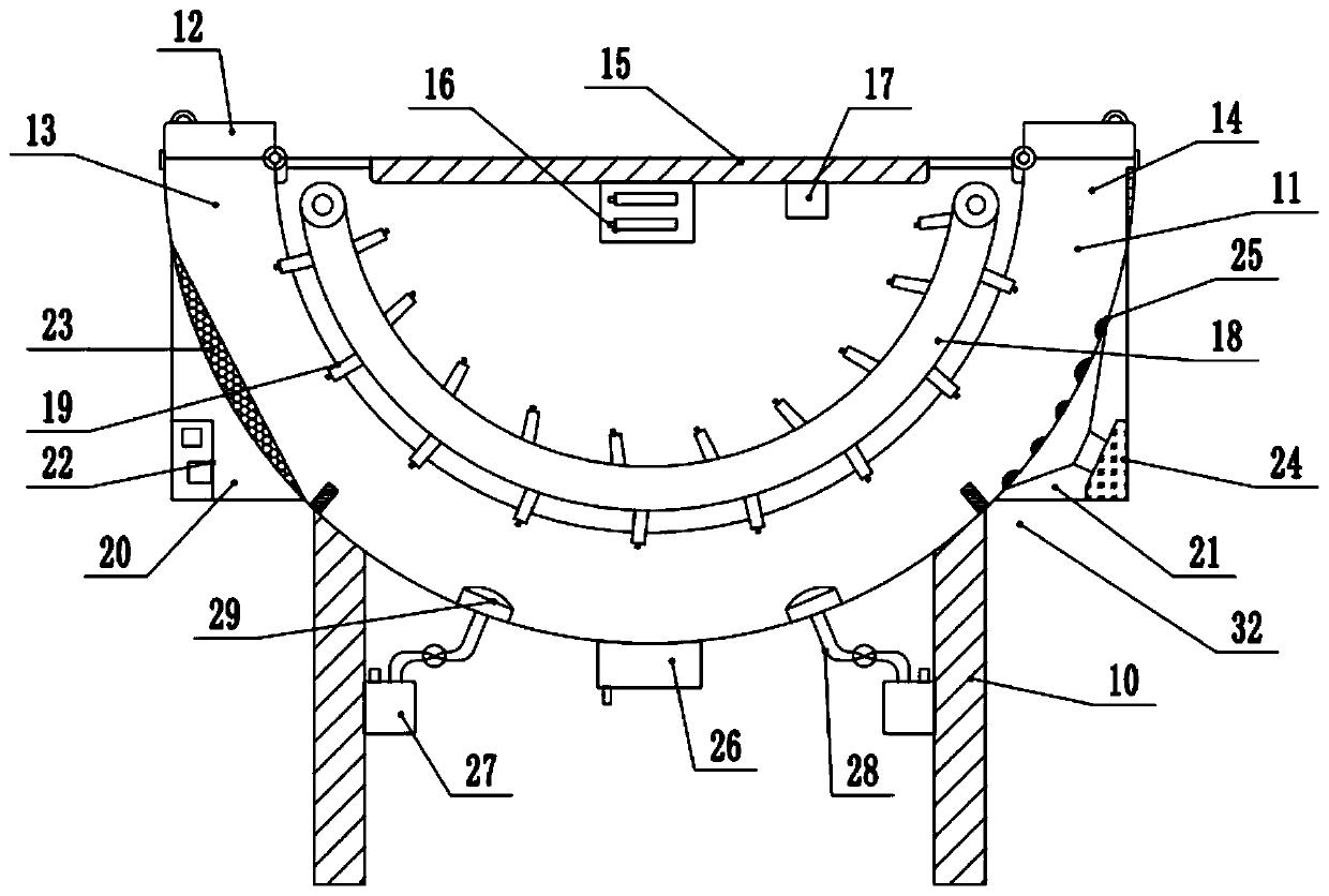
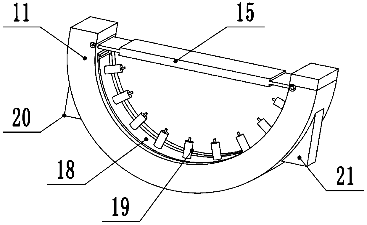
[0017] see Figure 1-3 , a mask cleaning device for surgery, comprising a cleaning chamber 11, an inlet 13, an outlet 14, a power supply 16, a water tank 27, a spray gun 29, and a body 32; the left and right sides of the bottom of the body 32 are supported by two groups of vertical legs 10. The body 32 is arranged in a semicircular structure, and a group of semicircular tubular cleaning chambers 11 are arranged on the inner lower side of the body 32. The upper left side of the cleaning chamber 11 is provided with an inlet 13, and the upper right side is provided with an outlet 14. The tops of the inlet 13 and the outlet 14 are rotatably connected with a set of cover plates 12 , and a set of pull rings for opening and closing the cover plates 12 are fixedly installed on the upper surface of the cover plates 12 . A group of horizontal mounting plates 15 are fixedly installed on the upper side of the middle part of the body 32, a power supply 16 is fixedly installed in the middle...

Embodiment 2

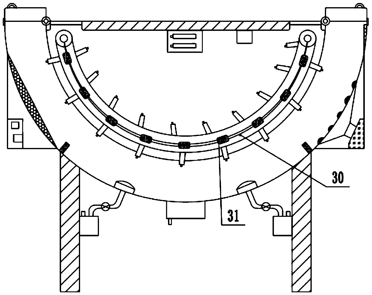
[0021] refer to image 3 , on the basis of Embodiment 1, a group of light strips 30 with the same structure as the conveyor belt 18 are arranged inside the conveyor belt 18, and several groups of ultraviolet lamps 31 are fixedly arranged on the top of the light strips 30 at equal intervals. The left and right ends are rotatably connected to the output drive shaft, the ultraviolet lamp 31 is electrically connected to the power supply 16, the ultraviolet lamp 31 is started and then the ultraviolet light is continuously emitted outward through the lamp belt 30, and then the masks on the left and right sides of the conveyor belt 18 are irradiated and sterilized Disinfection operation, thereby further improving the cleaning quality of the device to the mask.


PUM


Abstract

The invention relates to the field of medical supplies, and discloses a surgical mask cleaning device. The device comprises a cleaning cavity, an inlet, an outlet, a power supply, a water tank, a spray gun and a machine body; and a plurality of identical mounting frames are fixedly mounted on the outer surface of a conveying belt at equal intervals, a dust suction box and a drying box are fixedlymounted outside the left side and the right side of the cleaning cavity respectively, a filter screen is arranged at the joint between the dust suction box and the cleaning cavity, a dust removal areais arranged on the position, on the outer side of the filter screen, in the cleaning cavity, a hot air blower is fixedly mounted in the drying box, a transition groove communicates with the output end of the upper side of the hot air blower, a plurality of air exhaust holes communicate with the outer side of the transition groove, a drying area is arranged on the position, on the outer side of the air exhaust holes, in the cleaning cavity, and a cleaning area is arranged on the position, between the dust removal area and the drying area, in the cleaning cavity. The cleaning device has the advantages that the structures for dust removal, cleaning and drying are integrated into one structure, the cleaning speed is high, the efficiency is high, the practicability is high, and popularizationand use are facilitated.

Description

technical field [0001] The invention relates to the field of medical supplies, in particular to a surgical mask cleaning device. Background technique [0002] Chinese patent (notification number: CN 207806022 U, announcement date: 2018.09.04) discloses a portable oxygen mask cleaning device, the inside of the cleaning tube body is set as a cleaning liquid chamber, and the cleaning tube body is connected to a cleaning outer tube. The cleaning outer pipe is provided with a cleaning inner pipe, the inner wall of the cleaning outer pipe is provided with a chute, the outer wall of the cleaning inner pipe is provided with a slider, the slider is arranged in the chute, and a slide plate is arranged in the cleaning pipe body. A pull rod is fixedly connected to the axis of the slide plate, and the pull rod passes through the cleaning pipe body and is fixedly connected to the handle, and the outside of the cleaning pipe body is wrapped with a sponge cleaning layer. However, this clea...

Claims


Application Information

Patent Timeline
Patent Type & Authority Applications(China)
IPC IPC(8): B08B5/04B08B3/02B08B13/00F26B15/02F26B21/00A61L2/10
CPCA61L2/10A61L2202/17A61L2202/24B08B3/022B08B5/043B08B13/00F26B15/02F26B21/001F26B21/004
Inventor 雷斌宝雷斌磊邓攀
Owner 湖南利德森医疗器械有限公司
Why Eureka
Try Eureka