Express cabinet
A cabinet and column technology, applied in the field of express storage, can solve the problems of complex adjustment structure and high manufacturing cost of the storage cavity, and achieve the effects of low manufacturing cost, simple operation and high stability
- Summary
- Abstract
- Description
- Claims
- Application Information
AI Technical Summary
Problems solved by technology
Method used
Image
Examples
Embodiment 1
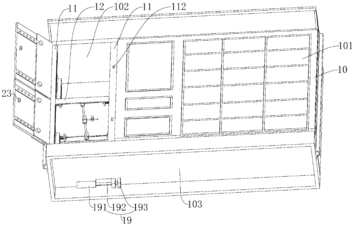
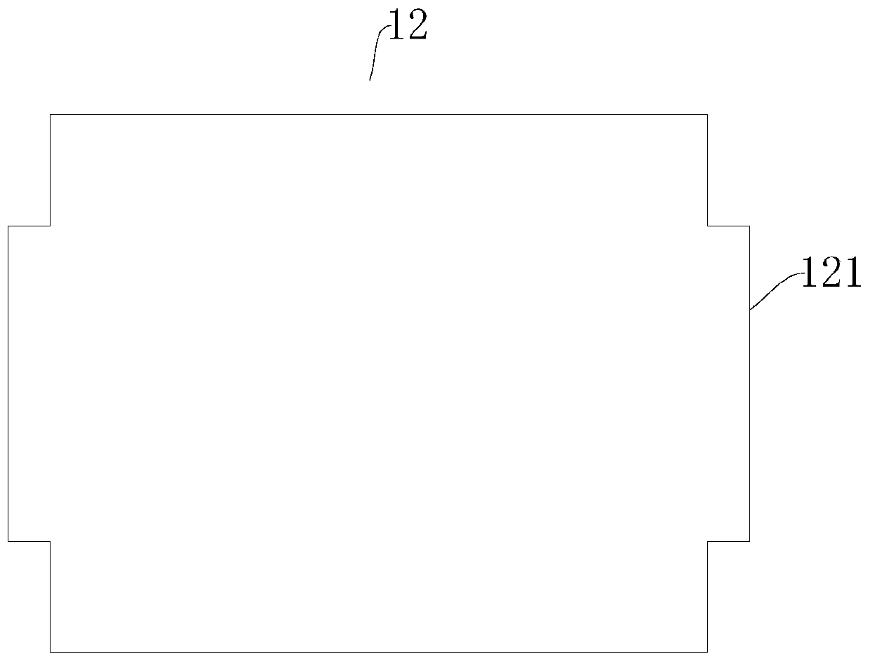
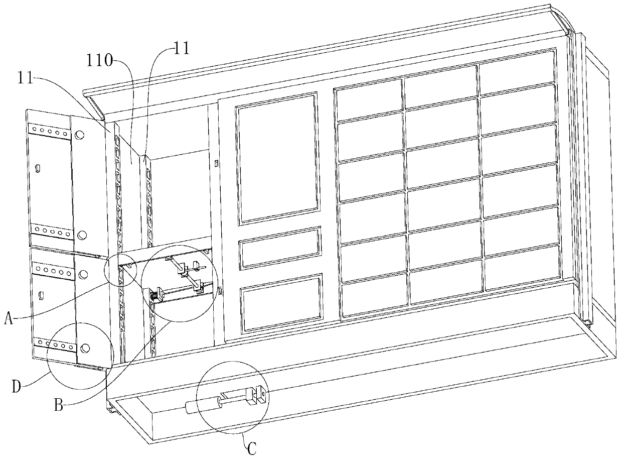
[0038] A kind of express cabinet, comprising a cabinet body 10, a plurality of storage cavities for storing express delivery are arranged in the cabinet body 10, the storage cavities include a fixed cavity 101 and a space-adjustable adjustment cavity 102, the cabinet body of this embodiment 10 is equipped with a number of at least four uprights 11 and a partition 12, the upright 11 is an adjustment column, the partition 12 is an adjustment plate, and the partition 12 is installed on the upright 11 and moves up and down along the upright 11 An adjustment cavity 102 is formed; a guide groove 110 is formed between two columns 11 on the same side, and first guide blocks 121 protruding horizontally to both sides of the partition plate 12 are fixed at both ends, and the partition plate 12 passes through the first guide block 121 is limited in the guide groove 110. With the first guide block 121, the partition plate 12 can be lifted and stabilized on the column 11. The inner wall of ...
Embodiment 2
[0047] Embodiment 2 has basically the same features as Embodiment 1, except that the lower sidewall 1111 of the slot 111 is a horizontal plane, the bottom surface 1112 of the slot 111 is an arc-shaped surface, and the bottom surface 1112 extends from the lower sidewall 1111 to the upper end of the slot 111. opening.
Embodiment 3
[0049] Embodiment 3 has basically the same features as Embodiment 1, except that the number of locking devices 13 is two, the two locking devices 13 are arranged diagonally, and the two locking devices 13 are respectively locked on two diagonally arranged When on the column 11, the quantity of the rotating device 14 is two, and the rotating shafts 142 of the two rotating devices 14 are connected through the coupling 18 and installed on the first fixed frame 141, and the end of the handle 15 is fixedly connected with the coupling 18, The two pulling wires 17 are wound on the respective take-up drums 144 in the same winding direction.
PUM
 Abstract
Description
Claims
Application Information
 - R&D
- Intellectual Property
- Life Sciences
- Materials
- Tech Scout
- Unparalleled Data Quality
- Higher Quality Content
- 60% Fewer Hallucinations
Browse by: Latest US Patents, China's latest patents, Technical Efficacy Thesaurus, Application Domain, Technology Topic, Popular Technical Reports.
© 2025 PatSnap. All rights reserved.Legal|Privacy policy|Modern Slavery Act Transparency Statement|Sitemap|About US| Contact US: help@patsnap.com


