Supercharge Your Innovation With Domain-Expert AI Agents!

Heating well structure

A technology of heating wells and heating rods, applied in the restoration of polluted soil, etc., can solve the problems of high cost, low heat transfer efficiency, single heat dissipation method, etc., and achieve the effect of improving heat diffusion efficiency

Pending Publication Date: 2020-02-28
上海康恒环境修复有限公司
View PDF0 Cites 4 Cited by
  • Summary
  • Abstract
  • Description
  • Claims
  • Application Information

AI Technical Summary

Problems solved by technology

[0004] However, the current in-situ thermal desorption method has low heat transfer efficiency due to the single heat dissipation method, resulting in low thermal desorption efficiency and high cost.

Method used


Image

  • Heating well structure
  • Heating well structure

Examples


Embodiment Construction

[0023] The heater well structure of the present invention will be described in more detail below in conjunction with schematic diagrams, wherein preferred embodiments of the present invention are shown, and it should be understood that those skilled in the art can modify the present invention described herein while still achieving the advantageous effects of the present invention. Therefore, the following description should be understood as the broad knowledge of those skilled in the art, but not as a limitation of the present invention.

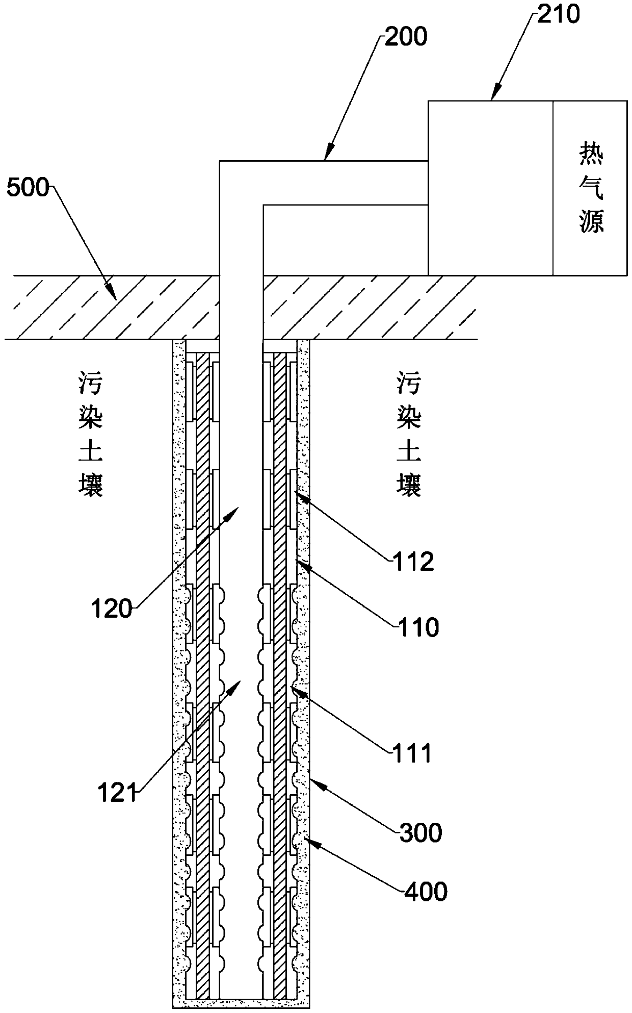
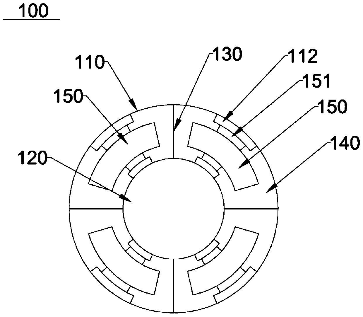
[0024] figure 1 A schematic diagram of the heater well structure in practice is shown. The heating well structure is mainly composed of four parts: outer casing 110 , inner casing 120 , heating rod 150 and gas injection pipe 200 .

[0025] The lower part of the outer casing 110 is the first screen section 111, and the length of the first screen section 111 accounts for 0.5-0.8 of the total length of the outer casing 110. Preferably, the len...


PUM


Abstract

The invention provides a heating well structure which comprises an outer sleeve, an inner sleeve, partition plates, heating rods and a gas injection pipe, and the lower portion of the outer sleeve isa first screen pipe section; the lower part of the inner sleeve is a second sieve tube section, and the inner sleeve is nested in the outer sleeve; the partition plates are located in an annular gap formed by the inner sleeve and the outer sleeve and evenly divide the annular gap into a plurality of cavities in the circumferential direction. At least one heating rod is arranged in each cavity; andthe gas injection pipe is connected with the top of the inner sleeve. According to the invention, the design of the inner sleeve and the outer sleeve is adopted, the plurality of heating rods are arranged in the annular gap between the two sleeves, and the pipeline of the inner sleeve is supplemented with compressed hot air, so that the diffusion of heat of a heating well to surrounding soil is accelerated, and the improvement of the heat diffusion efficiency of the heating well is realized.

Description

technical field [0001] The invention relates to a soil restoration device, in particular to a heating well structure. Background technique [0002] Thermal Desorption technology can be widely used in in-situ or ex-situ remediation of volatile organic compounds, semi-volatile organic compounds, petroleum hydrocarbons or mercury-contaminated sites. This technology heats the polluted soil and / or groundwater to close to or even exceed the boiling point of the target pollutants by means of direct or indirect heating, and selectively promotes the target pollutants to decompose, gasify, volatilize, Decompose or increase its mobility, so that the target pollutants can be separated from the soil medium and removed, so as to achieve the purpose of remediation of contaminated sites. [0003] The in-situ thermal desorption remediation technology does not need to excavate the contaminated soil. At present, two types of in-situ thermal desorption technologies are usually used: heat condu...

Claims


Application Information

Patent Timeline
IPC IPC(8): B09C1/06
CPCB09C1/06B09C1/065B09C2101/00
Inventor 李奉才刘荣琴余湛张章陈俊杰王加华李连福胡佳晨王欢王湘徽
Owner 上海康恒环境修复有限公司
Features
  • R&D
  • Intellectual Property
  • Life Sciences
  • Materials
  • Tech Scout
  • Unparalleled Data Quality
  • Higher Quality Content
  • 60% Fewer Hallucinations
Learn More