Cutting device for sheet metal processing

A technology for cutting equipment and sheet metal, applied in the field of sheet metal processing, can solve problems such as inability to fix sheet metal parts, increase the difficulty of equipment cleaning, and easily disperse and fly sparks, achieving good fixing effect, saving water resources and processing costs. , the effect of eliminating fire hazards

Pending Publication Date: 2020-02-28
苏州市金典精密制造有限公司
0 Cites 8 Cited by

AI-Extracted Technical Summary

Problems solved by technology

When the existing cutting equipment cuts sheet metal parts, a large amount of splashing high-temperature sparks will be generated, which poses a fire hazard and may cause harm to the operator. Moreover, the sparks are easy to disperse and ...

Method used

Clamping device 4 comprises top air cylinder 401, clamping plate 402 and some pressing down assemblies, and top air cylinder 401 is horizontally installed on the bed body 1, and clamping plate 402 is vertically arranged on top air cylinder 401 near the guide hole 5 On one side, the splint 402 is connected to the top air cylinder 401, and the pressing components are arranged side by side above the clamping plate 402. The pressing component includes a fixed frame 403, a downward pressure cylinder 404 and a pressing plate 405, and the fixed frame 403 is fixed on the top of the splint 402. The pressing cylinder 404 is installed vertically on the fixed frame 403 , and the pressing plate 405 is horizontally arranged on the side of the splint 402 close to the diversion hole 5 , and the pressing plate 405 is connected with the pressing cylinder 404 . The top air cylinder 401 can drive the clamping plate 402 to move left and right, and the downward pre...

Abstract

The invention relates to a cutting device for sheet metal processing. The cutting device comprises a lathe body, a walking frame and a laser cutting head, the lathe body is provided with a clamping device and a flow guide hole, a water circulation mechanism is arranged in the lathe body, the outer periphery of the laser cutting head is provided with a protective mechanism, the protective mechanismincludes a clamp, a hollow ring and a plurality of water spray components, each water spray component include a connection seat, a water curtain nozzle and a connection pipe, the water circulation mechanism includes a filter screen, a water tank, a circulation pump and a water supply joint, and the clamping device includes a jacking air cylinder, a clamping plate and a plurality of pressing components. In the cutting device for sheet metal processing, a water curtain can be used for cooling and intercepting high-temperature sparks to prevent the sparks from harming operators and prevent hidden fire hazards; collection of waste debris such as the sparks is simple and convenient to realize, and the difficulty of equipment cleaning is reduced; water recycling is realized, and water resourcesand processing cost are saved; and sheet metal parts in different shapes and sizes can be fixed, the application scope is wide, and the fixing effect is good.

Application Domain

Technology Topic

Image

  • Cutting device for sheet metal processing
  • Cutting device for sheet metal processing
  • Cutting device for sheet metal processing

Examples

  • Experimental program(1)

Example Embodiment

[0023] The present invention will now be described in further detail with reference to the drawings. These drawings are all simplified schematic diagrams, which merely illustrate the basic structure of the present invention in a schematic manner, so they only show the structures related to the present invention.
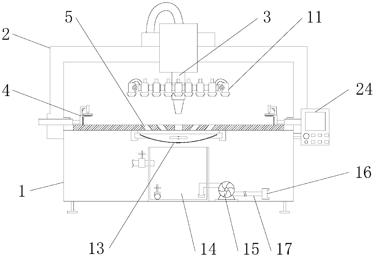
[0024] Such as figure 1 As shown, a cutting equipment for sheet metal processing includes a bed body 1, a walking frame 2 and a laser cutting head 3. The bed body 1 is provided with a clamping device 4 and a diversion hole 5, and the bed body 1 is provided with a water circulation mechanism , The outer periphery of the laser cutting head 3 is provided with a protective mechanism, which is connected with the water circulation mechanism;
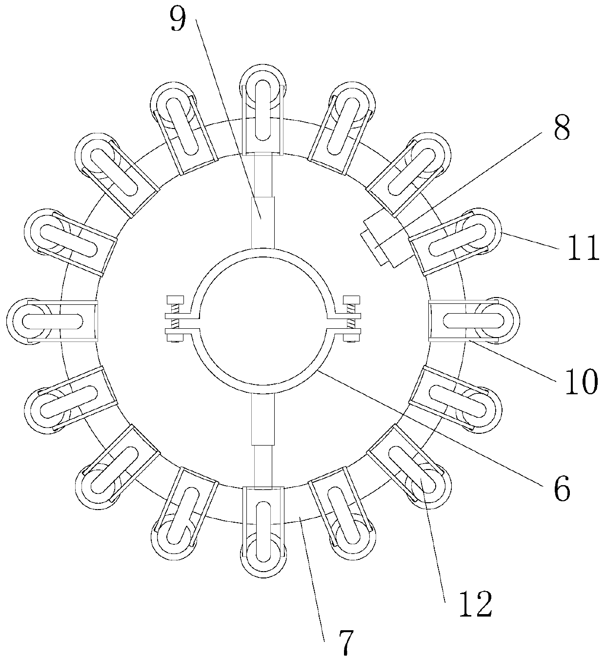
[0025] Such as figure 2 As shown, the protection mechanism includes a clamp 6, a hollow ring 7 and several water spray components. The clamp 6 is set on the laser cutting head 3, the hollow ring 7 is coaxially arranged on the outer periphery of the clamp 6, and the inner side of the hollow ring 7 is arranged There is a water inlet 8, the hollow ring 7 and the clamp 6 are connected by a connecting rod 9, and the water spray components are evenly distributed along the circumference of the hollow ring 7. The water spray components include a connecting seat 10, a water curtain nozzle 11 and a connecting pipe 12. The connecting seat 10 is fixed on the hollow ring 7, the water curtain sprinkler 11 is rotatably installed on the connecting seat 10, and the water outlet of the water curtain sprinkler 11 faces the bed 1, which communicates with the hollow ring 7 through the connecting pipe 12;
[0026] When in use, the clamp 6 is put on the laser cutting head 3 and locked and fixed. The water circulation mechanism supplies water to the water inlet 8 of the hollow ring 7, and the water flow in the hollow ring 7 is sprayed downward from the water curtain nozzle 11 through the connecting pipe 12 To form an annular water curtain, the water curtain nozzle 11 is rotated in advance to adjust the angle, and the size of the annular water curtain can also be changed. When cutting, when high-temperature sparks splash outwards, they will be intercepted by the water curtain and quickly cool down. Because the water flow always flows downwards, the water flow will exert a downward force on the sparks, making it difficult for the sparks to penetrate the water curtain, but will be moved down by the water. Wash away to avoid the adverse effects of high temperature sparks. In addition, the water flow can also cool the sheet metal parts to avoid the expansion and deformation of the cutting opening caused by the residual heat during cutting, which affects the cutting accuracy.
[0027] Such as image 3 As shown, the water circulation mechanism includes a filter screen 13, a water tank 14, a circulating pump 15, and a water supply connector 16. The filter screen 13 is in the shape of an arc with an arc facing upwards. The filter screen 13 is movably arranged below the diversion hole 5. The water tank 14 The water tank 14 and the circulating pump 15 are all fixed at the bottom of the bed 1, the opening of the water tank 14 is located at the bottom of the filter screen 13, the water supply connector 16 is butted with the water inlet 8, and the water supply connector 16, the circulating pump 15 and the water tank 14 are connected through the water pipe 17 in sequence.
[0028] When in use, the circulating pump 15 pumps water from the water tank 14, and delivers the clean water to the protection mechanism through the water pipe 17 and the water supply joint 16, and protects against splashing sparks. The sparks and water flow are mixed together and flow into the filter 13 through the diversion hole 5. In the process, waste debris such as sparks is intercepted by the filter 13, and the clean water continues to flow into the water tank 14 for recycling. The arc-shaped filter screen 13 facilitates the accumulation of waste debris. After the cutting is completed, the filter screen 13 can be drawn out to clean the waste debris.
[0029] Such as Figure 4 As shown, there are two clamping devices 4, the two clamping devices 4 are respectively placed on both sides of the bed body 1, and the diversion hole 5 is located between the two clamping devices 4. The two clamping devices 4 can fix both sides of the sheet metal parts, so that the sheet metal parts receive uniform force and improve the fixing effect.
[0030] The clamping device 4 includes a jacking cylinder 401, a clamping plate 402 and a number of pressing components. The jacking cylinder 401 is horizontally installed on the bed 1, and the clamping plate 402 is vertically arranged on the side of the jacking cylinder 401 close to the guide hole 5. The clamping plate 402 is connected to the jacking cylinder 401, and the pressing components are arranged side by side above the clamping plate 402. The pressing components include a fixing frame 403, a pressing cylinder 404 and a pressing plate 405. The fixing frame 403 is fixed above the clamping plate 402 and pressing the cylinder The 404 is vertically installed on the fixing frame 403, the pressing plate 405 is horizontally arranged on the side of the clamping plate 402 close to the diversion hole 5, and the pressing plate 405 is connected with the pressing cylinder 404. The jacking cylinder 401 can drive the clamping plate 402 to move left and right, and the pressing down cylinder 404 can drive the pressing plate 405 to move up and down. By adjusting the positions of the clamping plate 402 and the pressing plate 405, sheet metal parts of different shapes and sizes can be fixed, which has a wide range of applications. Driven by an air cylinder, the force is stable and the fixing effect is good.
[0031] A rubber layer 406 is provided on the side of the splint 402 close to the diversion hole 5 and under the pressure plate 405. The rubber layer 406 can protect the contact surface of the sheet metal part to avoid deformation and damage of the sheet metal part.
[0032] The connecting seat 10 is U-shaped, the water curtain nozzle 11 is arranged in the U-shaped mouth of the connecting seat 10, and the water curtain nozzle 11 is hinged to the connecting seat 10.
[0033] The connecting rod 9 is a telescopic rod, and its two ends are respectively fixedly connected with the hollow ring 7 and the clamp 6. When the clamp 6 is sleeved on different laser cutting heads 3, the distance between the clamp 6 and the hollow ring 7 is adjusted by the expansion and contraction of the connecting rod 9.
[0034] The filter screen 13 is a stainless steel filter screen. The stainless steel filter 13 has good corrosion resistance, is not easily deformed and damaged, and has a long service life.
[0035] The filter screen 13 is provided with a handle 18, and both sides are provided with guide units. The guide unit includes a guide rail 19 and a slider 20. The guide rail 19 is horizontally installed in the bed body 1, and the slider 20 is fixed on the filter screen 13. 20 is slidably connected to the guide rail 19. The handle 18 is provided to facilitate the operator to withdraw the filter screen 13 from the bed body 1 for waste recovery treatment. The guide rail 19 and the sliding block 20 can guide the movement of the filter screen 13 to make it move steadily in the front and rear directions.
[0036] The top and bottom of the water tank 14 are respectively provided with an inlet pipe 21 and a drain pipe 22, and both the inlet pipe 21 and the drain pipe 22 are provided with a control valve 23. The water inlet pipe 21 is used for filling water into the water tank 14, the drain pipe 22 is used for emptying the accumulated water in the water tank 14, and the control valve 23 is used for controlling the opening and closing of the water inlet pipe 21 or the drain pipe 22.
[0037] A man-machine interface 24 is provided on one side of the bed body 1. To facilitate the operator to control the equipment.
[0038] Working principle: When in use, place the sheet metal on the bed 1, the operator controls it through the man-machine interface 24, and the two splints 402 are driven by the respective push-in cylinders 401 to clamp the two sides of the sheet metal. The pressing air cylinder 404 drives the pressing plate 405 to press the upper end surface of the sheet metal part to realize the fixation of the sheet metal part. When cutting, the walking frame 2 drives the laser cutting head 3 to move and cut. At the same time, the circulating pump 15 pumps water from the water tank 14, and delivers the clean water to the hollow ring 7 through the water pipe 17 and the water supply connector 16. The water curtain nozzle on the connecting seat 10 is adjusted in advance At an angle of 11, the clear water in the hollow ring 7 is delivered to the water curtain nozzle 11 through the connecting pipe 12, the water curtain nozzle 11 sprays downwards, and a plurality of water curtain nozzles 11 together form an annular water curtain. When the high-temperature sparks generated by cutting splash outward, they will be intercepted by the water curtain and quickly cool down. Since the water flow always flows downwards, the water flow will exert a downward force on the sparks, and the sparks will be mixed into the water flow and flow downwards. At the same time, the clean water can also cool the cut of the sheet metal parts. Splashing waste debris such as sparks fall into the filter screen 13 from the guide hole 5 with the water flow. The curved filter screen 13 is conducive to the accumulation of waste debris, while the clean water falls from the bottom of the filter screen 13 into the water tank 14 for circulation. use. After the cutting is finished, the filter screen 13 is drawn out of the bed 1 through the handle 18 to clean up the accumulated waste.
[0039] The present invention is not limited to the above-mentioned specific implementations. For those of ordinary skill in the art, starting from the above-mentioned concept and without creative work, all the changes made fall within the protection scope of the present invention.

PUM

no PUM

Description & Claims & Application Information

We can also present the details of the Description, Claims and Application information to help users get a comprehensive understanding of the technical details of the patent, such as background art, summary of invention, brief description of drawings, description of embodiments, and other original content. On the other hand, users can also determine the specific scope of protection of the technology through the list of claims; as well as understand the changes in the life cycle of the technology with the presentation of the patent timeline. Login to view more.

Similar technology patents

Rubber-plastic mining air duct with reflective effect

InactiveCN107246278AEasy to walkAvoid causing harmTunnel/mines ventillationEngineeringTextile
Owner:阜宁县曙光合成革有限公司

Safety protection device of lifting belt or traction belt and use method of safety protection device

PendingCN113401783AAvoid causing harmBelt fasteningsSafety gearAutomotive engineeringTraction belt
Owner:CHINA THIRD METALLURGICAL GRP

Earthquake rescue equipment with life detection function

InactiveCN111976852AEasy rescueAvoid causing harmEndless track vehiclesGeological measurementsSprocketMarine engineering
Owner:象山奋凡消防科技有限公司

Building fire-fighting robot

PendingCN111228701AAvoid causing harmFire rescueWater pipeWater storage tank
Owner:IANGSU COLLEGE OF ENG & TECH

Biosafety cabinet with external scanning equipment

PendingCN111957357AAvoid causing harmImprove operational convenienceEnclosures/chambersSurveillance cameraStructural engineering
Owner:上海上净净化设备有限公司

Classification and recommendation of technical efficacy words

  • Eliminate fire hazards
  • Avoid causing harm

Preparation method of aluminum silver paste

InactiveCN102794452AEliminate fire hazardsNo emissionsSolventAluminium
Owner:HEFEI SUNRISE PIGMENTS

Dehumidifier fireproof method and system and dehumidifier

ActiveCN106563227AFire prevention methods are flexible and diverseEliminate fire hazardsFire rescueFire alarm electric actuationEngineeringFire risk
Owner:GD MIDEA AIR-CONDITIONING EQUIP CO LTD +1

Electrostatic spraying equipment

ActiveCN102179327AImprove safety and reliabilityEliminate fire hazardsFire rescueSpray discharge apparatusSpray nozzleEngineering
Owner:苏州必世洁机电有限公司

Method for producing graphite extruded plastic plate with CO2 foaming agent

InactiveCN109251349AEliminate fire hazardsEnergy savingPolystyrene particleFire retardant
Owner:穆振奎

Method for measuring and acquiring body image data of dairy cow

ActiveCN101904748AAvoid stress responseAvoid causing harmPhotogrammetry/videogrammetryPerson identificationBody imagesComputer processing
Owner:SHANGHAI INSTR RES INST

Child tricycle and front wheel thereof

InactiveCN106005237AAvoid causing harmChildren cyclesVehicle transmissionClutchThree-wheeled car
Owner:KUNSHAN LITTLE DINASAUR CHILD PROD

Pressure-adjustable grinding jig

InactiveCN109483382AOvercoming artificial grindingAvoid causing harmGrinding machinesGrinding/polishing safety devicesSlide plateIron filings
Owner:苏州嘉迈德电子科技有限公司
Why Eureka
Try Eureka