
Resistance recovery energy-saving ship

A resistance and hydraulic technology, applied in the field of resistance recovery and energy-saving ships, can solve the problems of cumbersome circuit energization system, reduced safety and reliability, reduced navigation stability, etc., and achieves increased stern propulsion capacity, fast capital return, and significant energy saving and environmental protection. Effect

Pending Publication Date: 2020-02-28
福安市雅铂阁电子商务有限公司
View PDF1 Cites 1 Cited by
  • Summary
  • Abstract
  • Description
  • Claims
  • Application Information

AI Technical Summary

Problems solved by technology

[0004] The energy-saving ship has the following disadvantages: 1. The manufacturing process is complicated, it is not easy to transform, the circuit power system is cumbersome, and the cost is high; 2. The resistance water of the ship's navigation cannot be recovered, and the new technology of converting it into power through a hydraulic converter plays an energy-saving role. 3. Affected by the climate, the navigation stability is reduced, the safety reliability is reduced, and the risk is increased

Method used


Image

  • Resistance recovery energy-saving ship
  • Resistance recovery energy-saving ship
  • Resistance recovery energy-saving ship

Examples


Embodiment 1

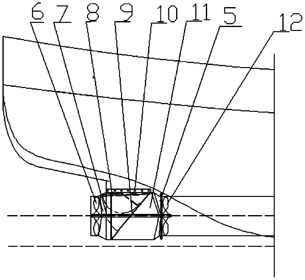
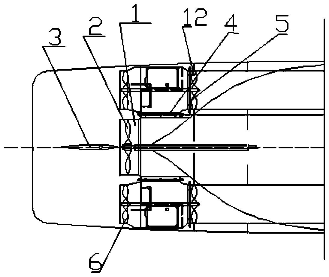
[0026] Such as Figure 1-6 As shown, a resistance recovery energy-saving ship includes a hull 21, a hydraulic converter 11, and a water turbine 12. A waterway 18 is arranged below the empty waterline in the hull 21, and one end of the waterway 18 is passed through the No. 1 method. The flange 4 is provided with a hydraulic converter 11, and the other end of the hydraulic converter 11 is connected to the No. 2 flange 5 of the propeller water supply port 17 of the main engine. One end of the shaft 7 is equipped with a water turbine 12 through a bolt, the other end of the water turbine connecting shaft 7 is installed with a negative machine propeller 6 through a bolt, and one end of the water turbine 12 is provided with a negative machine propeller water supply port 13, the hydraulic conversion The middle part of the device 11 is installed with a hydraulic converter internal isolation plate 16 through the mounting bracket, and one end of the water supply port 13 of the negative e...

Embodiment 2

[0037] Such as Figure 1-6 As shown, a resistance recovery energy-saving ship includes a hull 21, a hydraulic converter 11, and a water turbine 12. A waterway 18 is arranged below the empty waterline in the hull 21, and one end of the waterway 18 is passed through the No. 1 method. The flange 4 is provided with a hydraulic converter 11, and the other end of the hydraulic converter 11 is connected to the No. 2 flange 5 of the propeller water supply port 17 of the main engine. One end of the shaft 7 is equipped with a water turbine 12 through a bolt, the other end of the water turbine connecting shaft 7 is installed with a negative machine propeller 6 through a bolt, and one end of the water turbine 12 is provided with a negative machine propeller water supply port 13, the hydraulic conversion The middle part of the device 11 is installed with a hydraulic converter internal isolation plate 16 through the mounting bracket, and one end of the water supply port 13 of the negative e...


PUM


Abstract

The invention discloses a resistance recovery energy-saving ship, which comprises a hull, a hydraulic converter and a water turbine. A water passing channel is formed below a light waterline in the hull, the hydraulic converter is arranged at one end of the water passing channel through a first flange, the other end of the hydraulic converter is connected with a second flange of a main engine propeller water-supply opening, a water turbine connecting shaft is arranged in the hydraulic converter in a penetrating mode, the water turbine is mounted at one end of the water turbine connecting shaftthrough bolts, an auxiliary engine propeller is mounted at the other end of the water turbine connecting shaft through bolts, an auxiliary engine propeller water-supply opening is formed in one end of the water turbine, a hydraulic converter internal isolating plate is mounted in the middle of the hydraulic converter through a mounting frame, and a movable door control rod is arranged at one endof the auxiliary engine propeller water-supply opening in a penetrating mode. The novel resistance recovery energy-saving ship is diverse in function, easy to operate and convenient to produce, meetsvarious needs in use, and is suitable for being widely used and promoted.

Description

technical field [0001] The invention relates to the technical field of energy-saving ships, in particular to an energy-saving ship with resistance recovery. Background technique [0002] In the face of the huge consumption of global petrochemical resources, the shipping industry, as the main medium of resource transportation, is an important support for the global economy and is also a major energy consumer. Therefore, vigorously developing ship energy conservation and environmental protection has become a globalization. [0003] Patent No. CN201210375678.9 discloses an energy-saving ship. In the invention, the canvas can be converted into a solar panel, and the angle of the solar panel can be adjusted by rotating the lifting mobile machine and the rope. [0004] The energy-saving ship has the following disadvantages: 1. The manufacturing process is complicated, it is not easy to transform, the circuit power system is cumbersome, and the cost is high; 2. The resistance water...

Claims


Application Information

Patent Timeline
Patent Type & Authority Applications(China)
IPC IPC(8): B63H19/02F03B13/00F03B11/00
CPCB63H19/02F03B13/00F03B11/00Y02E10/20Y02T70/5236
Inventor 柯翰振
Owner 福安市雅铂阁电子商务有限公司
Learn More