Centrifugal spinning instrument

A centrifugal spinning and instrument technology, applied in textiles and papermaking, fiber processing, filament/thread forming, etc., can solve the problems of low production efficiency and achieve high production efficiency, convenient collection, and beneficial heating effects

Inactive Publication Date: 2020-02-28
WUJIANG FUAILIANG TEXTILE
View PDF0 Cites 9 Cited by
  • Summary
  • Abstract
  • Description
  • Claims
  • Application Information

AI Technical Summary

Problems solved by technology

[0005] The purpose of the present invention is to overcome the defects and problems of low production efficiency in the prior art and provide a centrifugal spinning instrument with high production efficiency

Method used


Image

  • Centrifugal spinning instrument
  • Centrifugal spinning instrument
  • Centrifugal spinning instrument

Examples


Embodiment Construction

[0029] The present invention will be described in further detail below in conjunction with the accompanying drawings and specific embodiments.

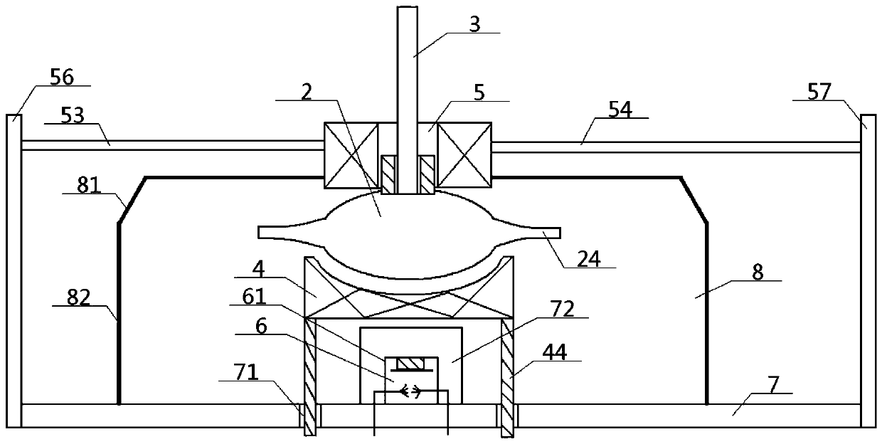
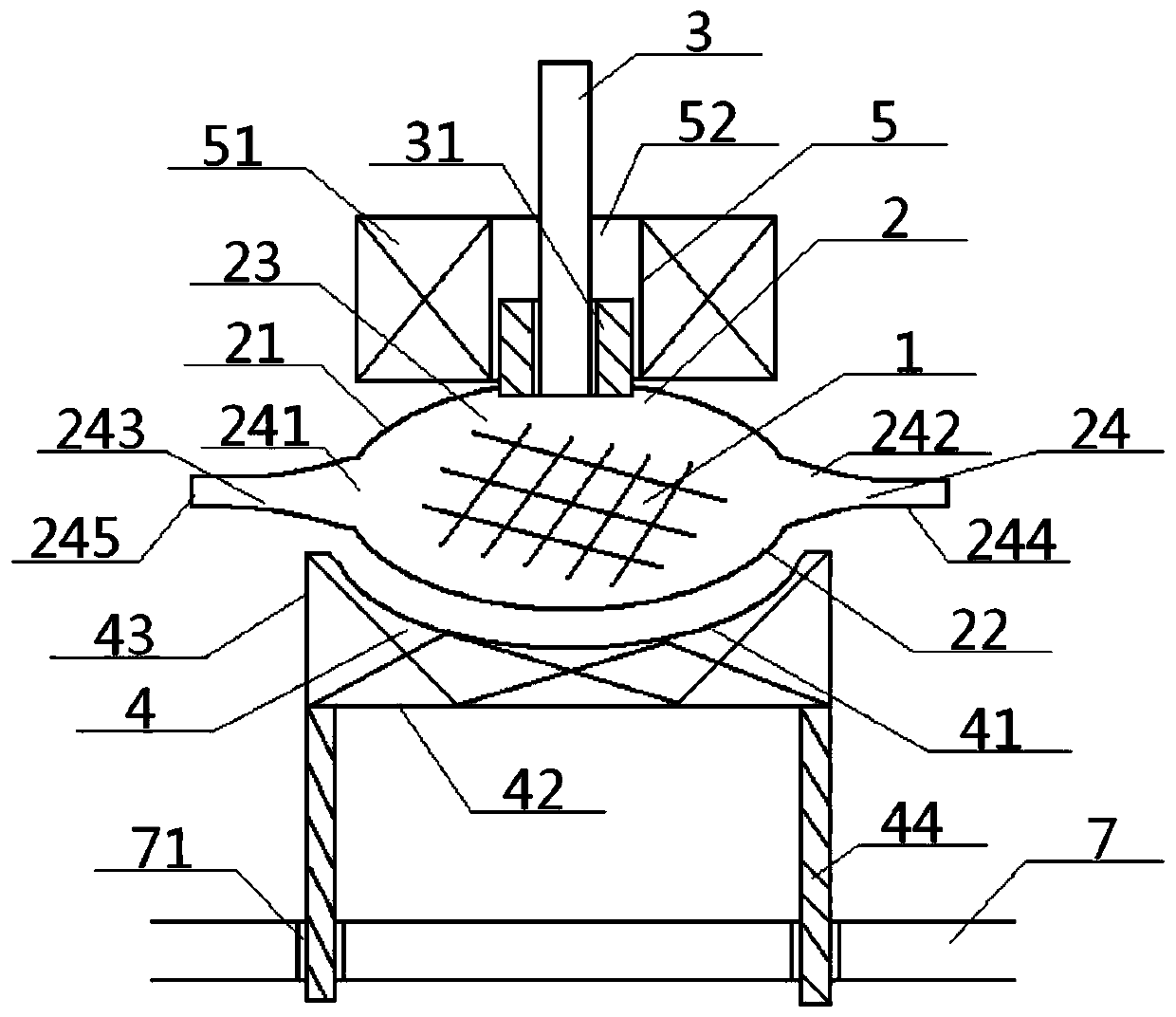
[0030] see Figure 1 to Figure 4 , a centrifugal spinning instrument, comprising a charging vessel 2 and a rotating shaft 3, the inside of the charging vessel 2 is provided with a fiber source 1, and the outside of the charging vessel 2 is connected to the rotating shaft 3;

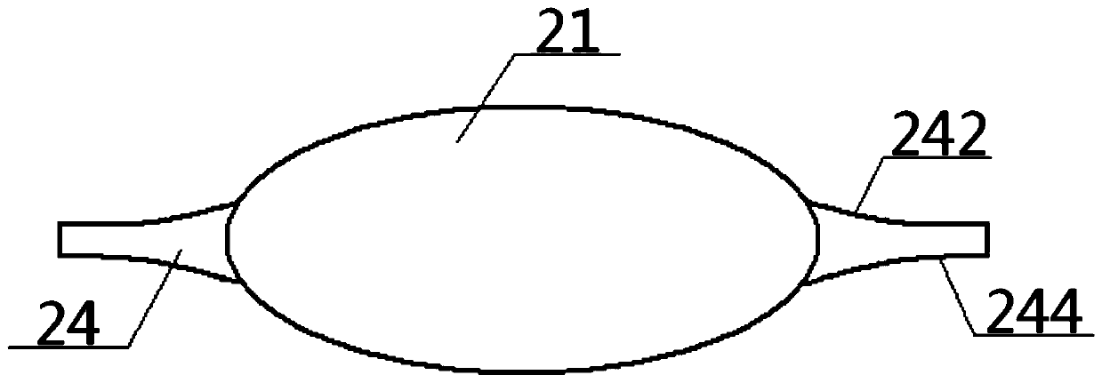
[0031]The charging vessel 2 is a spherical structure, comprising an upper spherical shell 21, a lower spherical shell 22 and a spherical shell cavity 23 between them, the spherical shell cavity 23 is provided with a fiber source 1, and the upper spherical shell 21 The middle part of the top surface is connected with the bottom of the rotating shaft 3, the bottom surface of the upper spherical shell 21 is connected with the top surface of the lower spherical shell 22, and the lower heating device 4 is arranged directly below the bottom surface of the lower spheric...


PUM

PropertyMeasurementUnit
angleaaaaaaaaaa
angleaaaaaaaaaa

Abstract

The invention provides a centrifugal spinning instrument. A loading vessel in the centrifugal spinning instrument has a spherical structure. The centrifugal spinning instrument comprises an upper spherical shell, a lower spherical shell and a spherical shell cavity, wherein a fiber source is arranged in the spherical shell cavity; the middle part of the top surface of the upper spherical shell isconnected with the bottom end of a rotating shaft; the bottom surface of the upper spherical shell is connected with the top surface of the lower spherical shell, and a lower heating device is arranged under the bottom surface of the lower spherical shell; an upper heating device is arranged over the top surface of the upper spherical shell; a junction of the upper spherical shell and the lower spherical shell is provided with a plurality of spinning nozzles which communicate with the spherical shell cavity; the spinning nozzles are lower than the junction of an upper barrel and a lower barrelin the collecting device; a temperature sensing box is arranged on a base connected with the bottom of the collecting device; and a temperature measuring sensor is arranged inside the temperature sensing box to monitor the temperature. According to the design, the production efficiency is high, the heating effect is good, the adjustability is high, and the collection effect is good.

Description

technical field [0001] The invention relates to a textile fiber manufacturing device, in particular to a centrifugal spinning instrument, which is particularly suitable for improving the production efficiency of textile fibers. Background technique [0002] Nanofibers refer to ultrafine fibers with a diameter of tens to hundreds of nanometers, which have unique advantages that other fibers cannot possess, such as very large specific surface area, ultrafine porosity, and good mechanical properties. In recent years, nanofibers have been widely used in textile materials, tissue engineering scaffolds, filter media, nanosensors, composite materials and other fields. [0003] The preparation of nanofibers has attracted the attention of experts and scholars at home and abroad. So far, there are many methods for preparing nanofibers, such as stretching method, microphase separation, template synthesis, self-assembly, electrospinning, etc. Among them, the electrospinning method is c...

Claims


Application Information

Patent Timeline
Patent Type & Authority Applications(China)
IPC IPC(8): D01D5/18
CPCD01D5/18
Inventor 张福明
Owner WUJIANG FUAILIANG TEXTILE
Why Eureka
Try Eureka