Water retaining dam and water flow regulation and control method thereof

A technology for retaining dams and dam bodies, applied in water conservancy projects, sea area projects, coastline protection, etc., can solve problems such as instability, inconvenient maintenance and repair, easy deformation, etc., and achieve the effect of easy maintenance and repair

Pending Publication Date: 2020-02-28
QUZHOU CITY RIVER HOLY WATER POWER AUTOMATIC FLAPGATE
View PDF0 Cites 2 Cited by
  • Summary
  • Abstract
  • Description
  • Claims
  • Application Information

AI Technical Summary

Problems solved by technology

[0004] 1. The driving mode of hydraulic cylinder and pneumatic cylinder is large, and it is usually installed under the gate, which is inconvenient for maintenance and repair.
[0005] 2. The airbag is in...

Method used


Image

  • Water retaining dam and water flow regulation and control method thereof
  • Water retaining dam and water flow regulation and control method thereof
  • Water retaining dam and water flow regulation and control method thereof

Examples


Embodiment 1

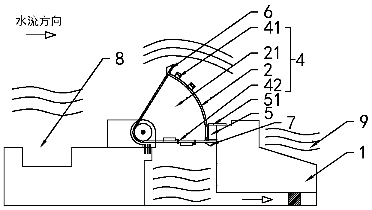
[0039] Such as Figure 1-Figure 5 As shown, the present invention discloses a dam, which comprises a dam body 1 and a gate 2 which is rotatably arranged on the dam body 1. In a specific embodiment of the invention, the gate 2 is equipped with a 1 turned upside-down power unit 3; the power unit 3 includes a ventilating chamber 21 arranged on the gate 2 for water-air exchange and a ventilating device 4 for exchanging water and air in the ventilating chamber 21. The air cavity 21 controls the turnover of the gate 2 in water through internal water-air exchange.

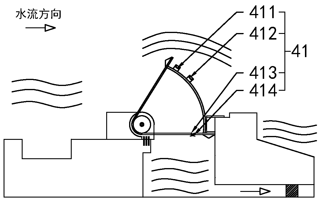
[0040] In a specific embodiment of the present invention, the ventilation device 4 includes a ventilation part 41 installed on the gate 2 and used for controlling the exchange of water and air in the ventilation cavity 21 by inflating or pumping air into the ventilation cavity 21 .

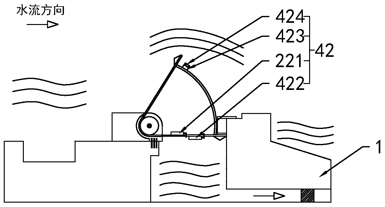
[0041]In a specific embodiment of the present invention, the ventilation device 4 further includes a water exchange unit 42 installed on th...

Embodiment 2

[0050] Embodiment 2, the difference with embodiment 1 is

[0051] Such as figure 1 , Figure 6 As shown, in the specific embodiment of the present invention: the dam body 1 is provided with a water stop plate 5 for limiting the displacement of the gate 2; The first support block 6 on the upper surface of the plate 5 and the second support block 7 against the lower surface of the water stop plate 5 when the gate 2 rises to the highest point.

[0052] In a specific embodiment of the present invention, the upper surface and the lower surface of the water-stop plate 5 are equipped with water-stop rubber 51 .

[0053] In a specific embodiment of the present invention, the waterproof rubber 51 includes an inner chamber 511 , and a number of air holes 512 are arranged on the side wall of the inner chamber 511 .

[0054] Through the above technical solution, when the gate is lowered, the first support plate is pressed against the upper surface of the water stop plate, so that the f...

Embodiment 3

[0055] Embodiment 3, differs from Embodiment 2 in that

[0056] Such as figure 1 As shown, in the specific embodiment of the present invention, the dam body 1 on the upstream side of the gate 2 is provided with a settling tank 8 for sedimentation.

[0057] By adopting the above-mentioned technical scheme, by setting up the sand settling tank, the water depth is increased through the sand settling tank, the flow rate of the water flow passing through here remains unchanged, the cross-sectional area becomes larger, and the velocity is reduced to reduce the flow velocity, which is beneficial Sediment is deposited, which protects the gate in this way.


PUM


Abstract

The invention relates to the technical filed of water retaining dams, in particular to a water retaining dam and a water flow regulation and control method thereof. According to the technical scheme,the water retaining dam comprises a dam body and a gate rotationally arranged on the dam body and is characterized in that a power unit is installed on the gate and is used for driving the gate to overturn on the dam body; the power unit comprises an air exchange cavity and an air exchange device, the air exchange cavity is arranged on the gate and is used for exchanging water and air, and the airexchange device is used for conducting water and air exchange in the air exchange cavity; the air exchange cavity controls overturn of the gate in water through inside water and air exchange; and thewater retaining dam and the water flow regulation and control method thereof have the beneficial effects that the water retaining dam is high in stability, high in safety performance and convenient to maintain.

Description

technical field [0001] The invention relates to the technical field of water retaining dams, in particular to a water retaining dam and a method for regulating water flow thereof. Background technique [0002] The dam is a water-retaining structure built under water. During use, the height of the gate on the dam is mainly adjusted by raising and lowering the height of the gate to realize the functions of water storage and flood discharge. [0003] At this stage, hydraulic cylinders, pneumatic cylinders, and airbag buoyancy are usually used to control the height of the gate; there are still some problems in this way: [0004] 1. The driving mode of hydraulic cylinder and pneumatic cylinder is large, and it is usually installed under the gate, which is inconvenient for maintenance and repair. [0005] 2. The height of the gate is controlled by airbag inflation and pumping. Since the airbag is a flexible structure, it is easily deformed underwater and there is a problem of ins...

Claims


Application Information

Patent Timeline
IPC IPC(8): E02B7/42E02B7/50E02B7/54E02B8/00E02B8/06
CPCE02B7/42E02B7/50E02B7/54E02B8/00E02B8/06
Inventor 周燕飞
Owner QUZHOU CITY RIVER HOLY WATER POWER AUTOMATIC FLAPGATE
Why Eureka
Try Eureka