Vibration and noise reduction device for air energy heat pump

An air energy heat pump, vibration reduction and noise reduction technology, applied to pump components, variable capacity pump components, liquid variable capacity machinery, etc., can solve problems such as a certain distance, high noise, and user inconvenience High dynamic response, good effect, and the effect of avoiding the reduction of structural strength

Pending Publication Date: 2020-02-28
HUNAN EWAVV NEW ENERGY TECH
View PDF0 Cites 6 Cited by
  • Summary
  • Abstract
  • Description
  • Claims
  • Application Information

AI Technical Summary

Problems solved by technology

[0002] The air source heat pump works through medium heat exchange. Its production makes people's life more convenient. The function of the air source heat pump not only saves time, but also helps users to carry out life and work better. However, the traditional The noise of the air energy heat pump is particularly loud, especially when the compressor is running, the noise reaches 80 decibels, which brings inconvenience to users
[0003] The noise in acoustic media such as air and water originates, on the one hand, from the propagation effect of elastic waves in the structure, and the mutual coupling between the structural elastic wave and the surrounding acoustic medium (structural sound), on the other hand, it is due to the interaction of sound field acoustic waves (air sound); therefore, the control of noise in the acoustic medium should be carried out from the above two directions, that is, to control the elastic wave behavior in the structure and the sound wave in the air, so as to reduce vibration and noise in the acoustic space; the wave control method can be divided into The second category: active methods and passive methods; active methods generally require external energy, and the system implementation is relatively complicated, and there is still a certain distance from practicality, so passive methods are commonly used in engineering structures; existing passive methods mostly use Damping materials and sound-absorbing materials attenuate bending waves and sound waves, but with the development of science and technology and society, people have higher and higher requirements for equipment comfort, reliability, safety and durability. Therefore, the existing Passive methods can no longer meet the design requirements; it is more necessary to vigorously develop new theories, new methods and new technologies for structural vibration and noise reduction; the concept of acoustic black holes has set off a new wave for the realization of "artificial manipulation of wave propagation in elastic media and structures". It opened a new chapter, and also provided a new opportunity for theoretical and technological breakthroughs in structural vibration and noise reduction.

Method used


Image

  • Vibration and noise reduction device for air energy heat pump
  • Vibration and noise reduction device for air energy heat pump
  • Vibration and noise reduction device for air energy heat pump

Examples


Embodiment 1

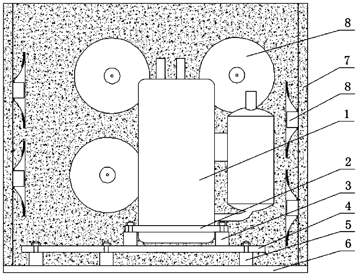
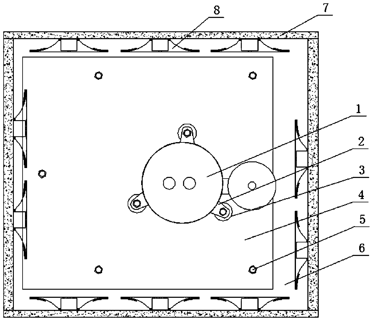
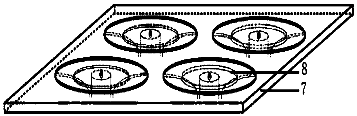
[0024] Such as Figure 1-4 As shown, a vibration and noise reduction device for an air energy heat pump includes a compressor 1, a passive vibration and noise reduction mechanism installed around the compressor 1 and an acoustic black hole noise reduction mechanism 8, and the passive vibration and noise reduction mechanism It includes a layer of damping elements 3, a transition plate 4, a second layer of damping elements 5, a base 6, and sound-absorbing cotton 7. The surrounding of the base 6 is vertically provided with sound-absorbing cotton 7, and the upper part is provided with several second-layer damping elements. 5. A transition plate 4 is installed on the two-layer damping element 5, and several layers of vibration-damping elements 3 are installed on the transition plate 4, and the layer of vibration-damping elements 3 is connected to the compressor 1 from below; the acoustic black hole The noise reduction mechanism 8 is installed on the sound-absorbing cotton 7 around ...

Embodiment 2

[0028] On the basis of Embodiment 1, the first layer of damping element 3 is a vibration isolator or a shock absorber, and the second layer of vibration damping element 5 is a vibration isolator or a rigid pad or a shock absorber, which can be freely selected according to design requirements. Select the first and second layers of damping elements 5 .

Embodiment 3

[0030] On the basis of Embodiment 2, the bottom of the compressor 1 is provided with three clevis buckles 2, and there are three damping elements 3 on the first layer, which are respectively connected with the three lug bolts of the three clevis buckles 2; making the installation more stable and quick .


PUM


Abstract

The invention discloses a vibration and noise reduction device for an air energy heat pump. The vibration and noise reduction device includes a compressor, and further includes a passive vibration andnoise reduction mechanism and an acoustic black hole noise reduction mechanism which are installed around the compressor, the passive vibration and noise reduction mechanism includes first-layer vibration reduction elements, a transition plate, two-layer vibration reduction elements, a base and sound-absorbing cotton, the sound-absorbing cotton is vertically arranged around the base, the multipletwo-layer vibration reduction elements are arranged on the upper part of the base, the transition plate is installed on the two-layer vibration reduction elements, and the multiple first-layer vibration reduction elements are installed on the transition plate, the first-layer vibration reduction elements are connected to the compressor from the lower part, and the acoustic black hole noise reduction mechanism is installed around the compressor on the sound-absorbing cotton. According to the vibration and noise reduction device, the purpose of energy absorption or vibration and noise reductionis achieved through combination of passive vibration and noise reduction and acoustic black hole noise reduction, thus full spectrum band noise reduction is realized, limitation that low frequency isdifficult to achieve by using traditional acoustic black holes to reduce vibration and noise is remedied, and thus the effects of vibration and noise reduction are better.

Description

technical field [0001] The invention relates to a vibration and noise reduction device, in particular to a vibration and noise reduction device for an air energy heat pump. Background technique [0002] The air source heat pump works through medium heat exchange. Its production makes people's life more convenient. The function of the air source heat pump not only saves time, but also helps users to carry out life and work better. However, the traditional The noise of the air energy heat pump is particularly loud, especially when the compressor is running, the noise reaches 80 decibels, which brings inconvenience to the users. [0003] The noise in acoustic media such as air and water originates, on the one hand, from the propagation effect of elastic waves in the structure, and the mutual coupling between the structural elastic wave and the surrounding acoustic medium (structural sound), on the other hand, it is due to the interaction of sound field acoustic waves (air soun...

Claims


Application Information

Patent Timeline
Patent Type & Authority Applications(China)
IPC IPC(8): F04B39/00G10K11/16G10K11/162
CPCF04B39/0083F04B39/0044F04B39/0088F04B39/005G10K11/16G10K11/162
Inventor 张亚宁曹彦雄
Owner HUNAN EWAVV NEW ENERGY TECH
Why Eureka
Try Eureka