Strain gauge dynamic calibration method and device based on non-contact scanning measurement

A non-contact, dynamic calibration technology, applied in the direction of measuring devices, instruments, etc., can solve the problems of not considering the change of motion state and time parameters, the problem of dynamic strain calibration without breakthrough, and the problem of tracing the source of uncomfortable dynamic strain field. Effects of simple differential calculation, improvement of reliability and stability, and improvement of data processing efficiency

Inactive Publication Date: 2020-02-28
BEIJING CHANGCHENG INST OF METROLOGY & MEASUREMENT AVIATION IND CORP OF CHINA
View PDF8 Cites 5 Cited by
  • Summary
  • Abstract
  • Description
  • Claims
  • Application Information

AI Technical Summary

Problems solved by technology

Due to the difficulty in the occurrence and traceability of dynamic strain, there has been no breakthrough in the calibration of dynamic strain
The current strain traceability method can only measure the static uniform strain field, and there is no high-precision traceability method for dynamic strain

Method used


Image

  • Strain gauge dynamic calibration method and device based on non-contact scanning measurement
  • Strain gauge dynamic calibration method and device based on non-contact scanning measurement
  • Strain gauge dynamic calibration method and device based on non-contact scanning measurement

Examples


Embodiment 1

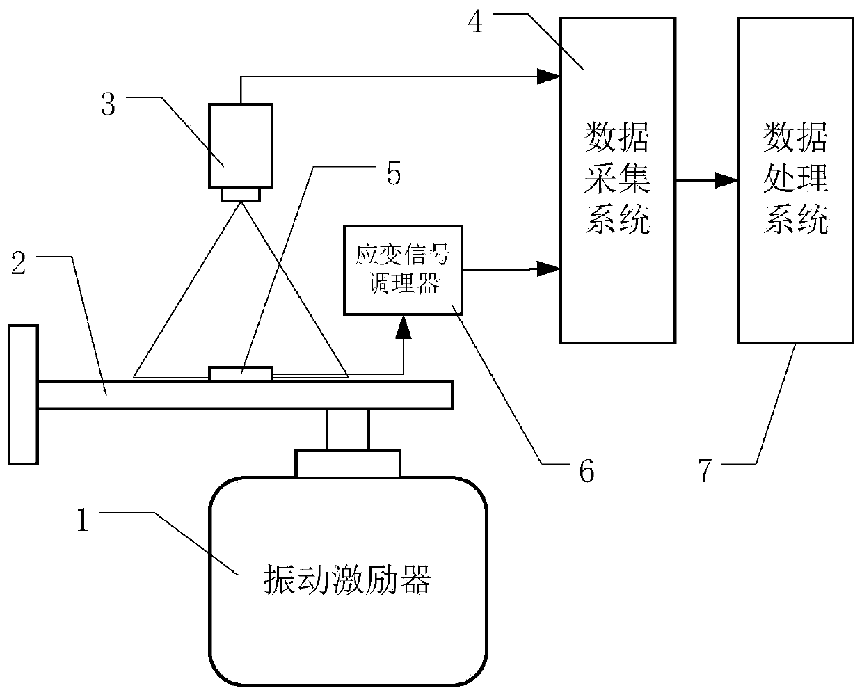
[0033] Such as figure 1 As shown, the strain gauge dynamic calibration device based on non-contact scanning measurement disclosed in this embodiment includes a vibration exciter 1, a cantilever beam 2, a scanning laser vibrometer 3, a data acquisition system 4, a strain gauge to be calibrated 5, a strain gauge Signal conditioner 6, data processing system 7.

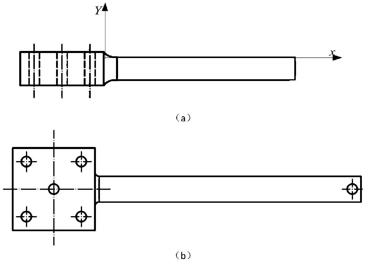
[0034] First, select a cantilever beam 2 with a constant section with a length of 200 mm, a thickness of 10 mm, and a first-order natural frequency of 1 kHz. One end of the cantilever beam 2 is installed on the vibration exciter 1, and the other end is placed on a fixed support. The abscissa of the fixed end is is 0. Install the strain gauge 5 to be calibrated at 20 mm from the upper surface of the cantilever beam 2 . The scanning laser vibrometer 3 is located above the cantilever beam 2. The scanning laser vibrometer 3 is installed on the guide rail and can move along the guide rail. The signals output by the scanning ...

Embodiment 2

[0049] Such as figure 1 As shown, the strain gauge dynamic calibration device based on non-contact scanning measurement disclosed in this embodiment includes a vibration exciter 1, a cantilever beam 2, a scanning laser vibrometer 3, a data acquisition system 4, a strain gauge to be calibrated 5, a strain gauge Signal conditioner 6, data processing system 7.

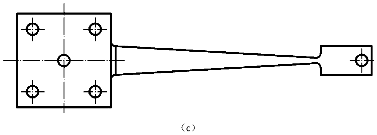
[0050] First, select a cantilever beam 2 of equal strength with a length of 200 mm, a thickness of 10 mm, and a first-order natural frequency of 1 kHz, install one end of the cantilever beam 2 on the vibration exciter 1, and place the other end on a fixed support, and turn on the vibration exciter Make the equal-strength cantilever beam 2 in a stable vibration state, the vibration frequency is 10 Hz, the test method and steps are the same as the implementation method 1.

[0051] Step 1: Turn on the vibration exciter 1 to make the constant-section cantilever beam 2 in a stable vibration state with a vibration frequency of...


PUM

PropertyMeasurementUnit
Lengthaaaaaaaaaa
Thicknessaaaaaaaaaa

Abstract

The invention discloses a strain gauge dynamic calibration method and device based on non-contact scanning measurement, and belongs to the field of metering test. The implementation method comprises the steps that the output of a controller of a vibration exciter is adjusted to reach a required vibration frequency, and the output of the power amplifier of the vibration exciter is adjusted to reacha required amplitude; a cantilever beam is kept in a sinusoidal vibration state with the stable frequency through the vibration exciter; N measuring points at equal intervals are selected on the surface of the cantilever beam in the axial direction of the beam, and deflection measurement is performed on the surface of the cantilever beam in a forced vibration state; the peak deflection curve of the surface of the cantilever beam is fit according to the obtained deflection state of each measurement point; the peak deflection curve is converted into a strain peak curve; and a calibrated straingauge is installed in the calibration area of the cantilever beam, and the output value of the calibrated strain gauge is compared with a standard strain value, thereby achieving the dynamic strain calibration. The invention further discloses a strain gauge dynamic calibration device based on non-contact scanning measurement. The structure is simple, and the operation is easy.

Description

technical field [0001] The invention relates to a strain gauge dynamic calibration method and device based on non-contact scanning measurement, which belongs to the field of measurement and testing. Background technique [0002] Dynamic strain testing is an important method for material testing, structural dynamic strength assessment and health monitoring. For accurate measurement of dynamic strain, calibration of the strain gauge is required. The research on the calibration of strain measurement has been carried out very early at home and abroad, but it has been stuck in the direction of static strain calibration. Due to the difficulty in the occurrence and traceability of dynamic strain, there has been no breakthrough in the calibration of dynamic strain. In the calibration process of dynamic strain, it is necessary to accurately measure the strain value of the dynamic strain excitation source in real time to realize the traceability of the dynamic strain. In the proces...

Claims


Application Information

Patent Timeline
IPC IPC(8): G01B21/32
CPCG01B21/042G01B21/32
Inventor 尹肖张力隋广慧薛景锋李泓洋黄彩霞
Owner BEIJING CHANGCHENG INST OF METROLOGY & MEASUREMENT AVIATION IND CORP OF CHINA
Why Eureka
Try Eureka