Visible light and short-wave infrared dual-waveband common-aperture long-focus optical system

A short-wave infrared and optical system technology, applied in optics, optical components, instruments, etc., can solve problems such as large difference in visual experience, expensive infrared materials, and easy to affect target recognition, so as to improve the utilization rate of light energy and enhance the target Reconnaissance ability, reduced length effect

Active Publication Date: 2020-02-28
FUJIAN FORECAM OPTICS CO LTD
9 Cites 6 Cited by

AI-Extracted Technical Summary

Problems solved by technology

[0003] Visible light imaging technology is mature and can achieve high-resolution detection, but it is easily affected by bad weather and is not suitable for weak light environments such as night; infrared thermal imaging technology uses the infrared radiation characteristics of the detected target to identify targets, which is anti-interference, It has the adva...

Method used

As shown in Figure 1, a kind of visible light of the present invention, short-wave infrared dual-band co-aperture telephoto optical system, described optical system comprises public mirror group A, beam splitting prism B, visible light mirror group C and short-wave infrared mirror group D , the common mirror group A and the beam-splitting prism B are arranged from left to right along the incident light path, and the beam-splitting prism B divides the outgoing light from the common mirror group A into two paths on the right side and the upper side, and the two optical paths on the right side and the upper side are respectively Simultaneous imaging is performed through the visible light mirror group C and the short-wave infrared mirror group D. The common mirror group A, the beam splitting prism B and the visible light mirror group C form a visible light path, which is imaged by a visible light detector; the common mirror group A, the beam splitting prism B and the short-wave infrared mirror group D form a short-wave infrared light path, which is received and imaged by the short-wave infrared detector...

Abstract

The invention relates to a visible light and short-wave infrared dual-waveband common-aperture long-focus optical system, which comprises a public mirror group A, a beam splitting prism B, a visible light mirror group C and a short-wave infrared mirror group D. The public mirror group A and the beam splitting prism B are arranged from left to right along an incident light path, incident light fromthe public mirror group A is divided into two ways through the beam splitting prism B, the two ways of light paths are imaged through the visible light mirror group C and the short-wave infrared mirror group D, and a visible light path is formed by the public mirror group A, the beam splitting prism B and the visible light mirror group C; and a short-wave infrared light path is formed by the public mirror group A, the beam splitting prism B and the short-wave infrared mirror group D. The optical system is compact in structure, a target can be simultaneously subjected to visible light and short-wave infrared dual-waveband imaging, the two waveband light paths have the same relative aperture and focal length, and all-weather long-range target high-resolution imaging can be achieved.

Application Domain

Optical elements

Technology Topic

Wave bandPrism +9

Image

  • Visible light and short-wave infrared dual-waveband common-aperture long-focus optical system
  • Visible light and short-wave infrared dual-waveband common-aperture long-focus optical system
  • Visible light and short-wave infrared dual-waveband common-aperture long-focus optical system

Examples

  • Experimental program(1)

Example Embodiment

[0020] The present invention will be further described in detail below with reference to the drawings and specific embodiments.
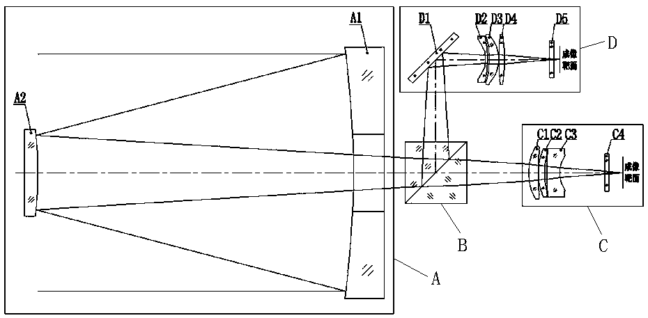
[0021] Such as figure 1 As shown, the present invention is a visible light and short-wave infrared dual-band common aperture telephoto optical system. The optical system includes a common mirror group A, a beam splitter B, a visible light mirror group C, and a short-wave infrared mirror group D. The common mirror group A and beam splitting prism B are arranged from left to right along the incident light path. Beam splitting prism B divides the emitted light from the common lens group A into two paths on the right side and upper side. The two paths of light on the right side and the top side respectively pass through the visible light mirror group C and The shortwave infrared lens group D performs simultaneous imaging, the common lens group A, the beam splitter B, and the visible light lens group C form a visible light optical path, and the visible light detector receives imaging; the common lens group A, the beam splitter prism B, and the shortwave infrared lens group D forms a short-wave infrared light path, which is imaged by a short-wave infrared detector. By imaging the target's visible light band and short-wave infrared band simultaneously, the light energy utilization rate is improved, and the system's target detection ability is enhanced; and the dual-band shared optical path adopts a reflective optical path structure, which eliminates chromatic aberration, especially the secondary spectrum for the telephoto system The influence of this helps to improve the imaging quality of the optical system and effectively reduces the length of the system.
[0022] In this embodiment, the visible light optical path and the short-wave infrared optical path have the same relative aperture and focal length, which realizes simultaneous imaging of visible light (0.4-0.9 μm) and short-wave infrared (0.9-1.7 μm) dual-band, which improves the light energy Utilization rate.
[0023] In this embodiment, the common mirror group A includes a secondary mirror A2 and a primary mirror A1 arranged in order from left to right; the visible light mirror group C is located on the rear side of the beam splitting prism B, and the visible light mirror group C includes The positive crescent lens C1, the positive crescent lens C2, the negative crescent lens C3, and the visible light filter C4 are sequentially set to the right; the short-wave infrared lens group D is located on the upper side of the beam splitter B, and the short-wave infrared lens group D includes The mirror D1, the negative crescent lens D2, the positive crescent lens D3, the biconvex lens D4, and the short-wave infrared color filter D5 are arranged in sequence on the right.
[0024] In this embodiment, the reflective surface of the primary reflector A1 is a quadric surface with a central opening, wherein the conic constant is -1.255; the reflective surface of the secondary reflector A2 is a quadric surface, and the conic The constant is -3.821.
[0025] In this embodiment, the distance between the primary reflector A1 and the secondary reflector A2 is 155.0 mm.
[0026] In this embodiment, both the primary reflector A1 and the secondary reflector A2 are made of K9 glass material.
[0027] In this embodiment, the dichroic surface of the dichroic prism B is coated with a dichroic film to realize the transmission of visible light while reflecting short-wave infrared light.
[0028] In this embodiment, the reflector D1 is a plane reflector, and the included angle with the optical axis of the system is 45°, which deflects the shortwave infrared light path and reduces the size of the entire system.
[0029] In this embodiment, the center distance between the beam splitting prism B and the visible light mirror group C is 27.0 mm, and the center distance between the beam splitting prism B and the short-wave infrared mirror group D is 32.3 mm.
[0030] In this embodiment, in the visible light lens group C, the air gap between the positive crescent lens C1 and the positive crescent lens C2 is 0.14 mm, and the air gap between the positive crescent lens C2 and the negative crescent lens C3 is 1.33 mm, the air gap between the negative crescent lens C3 and the visible light filter C4 is 26.00mm; in the shortwave infrared lens group D, the air gap between the mirror D1 and the negative crescent lens D2 is 19.82mm, The air gap between the negative crescent lens D2 and the positive crescent lens D3 is 0.74mm, the air gap between the positive crescent lens D3 and the double convex lens D4 is 0.21mm, the double convex lens D4 and the short-wave infrared color filter The air gap of D5 is 22.00mm.
[0031] In this embodiment, each lens of the visible light lens group C needs to meet the parameter requirements shown in Table 1.
[0032] Table 1 Parameter table of lens C of visible light lens group:
[0033]
[0034] In this embodiment, each lens of the short-wave infrared lens group D needs to meet the parameter requirements shown in Table 2.
[0035] Table 2 Lens parameter table of shortwave infrared lens group:
[0036]
[0037] The optical system has a focal length of 750mm, a relative aperture of 1/6.0, a visible light band modulation transfer function with a spatial frequency of 145lp/mm, and a short-wave infrared band modulation transfer function with a spatial frequency of 34lp/mm. The dual-band transfer functions are close to the diffraction limit, and the imaging is excellent. High resolution, can realize all-weather long-distance target detection.
[0038] The foregoing descriptions are only preferred embodiments of the present invention, and all equivalent changes and modifications made in accordance with the scope of the patent application of the present invention shall fall within the scope of the present invention.

PUM

no PUM

Description & Claims & Application Information

We can also present the details of the Description, Claims and Application information to help users get a comprehensive understanding of the technical details of the patent, such as background art, summary of invention, brief description of drawings, description of embodiments, and other original content. On the other hand, users can also determine the specific scope of protection of the technology through the list of claims; as well as understand the changes in the life cycle of the technology with the presentation of the patent timeline. Login to view more.

Similar technology patents

Polarization conversion device

Owner:CHONGQING IQIYI INTELLIGENT TECHNOLOGY CO LTD

Method for breeding three-line rice strong restoring line H570

PendingCN105746340AIncrease cut-off areaImprove light energy utilization
Owner:CHINA NAT RICE RES INST

Reflector, backlight module and television set

ActiveCN102588882AImprove light energy utilizationImproved dynamic area contrast and resolution
Owner:GUANGDONG HISENSE ELECTRONICS CO LTD

Classification and recommendation of technical efficacy words

Why Eureka
Try Eureka