
Wire cutting device based on mold processing

A mold processing and wire cutting technology, applied in attachments, electric processing equipment, metal processing equipment, etc., can solve the problems of wasting water resources, inability to guarantee accuracy, and disadvantageous device use, and increase the accuracy of adjustment, Adjust the effect of saving time and effort and saving the cost of use

Inactive Publication Date: 2020-03-06
嘉兴德衡智能装备有限公司
View PDF6 Cites 1 Cited by
  • Summary
  • Abstract
  • Description
  • Claims
  • Application Information

AI Technical Summary

Problems solved by technology

[0003] The Chinese patent discloses a wire cutting device for mold processing (authorized announcement number N209175069U). This patent technology uses the electrode wire to enter the communication hole, and the working fluid in the spray pipe enters the communication hole and sprays on the electrode wire. Together with the electrode wire, it is output from the outlet of the connecting hole, which can cool down the electrode wire conveniently and quickly, thereby improving the quality of pipe wire cutting. However, most of the wire cutting devices based on mold processing on the market currently have no cooling liquid circulation device. Waste of water resources, the cutting residue cannot be filtered, which is not conducive to the recycling of the residue and can not play the role of energy saving and emission reduction. Most of the mold adjustment is manual adjustment, which is inconvenient to use, time-consuming and laborious to adjust, and the accuracy of the adjustment cannot be guaranteed. It is not conducive to the accuracy of device cutting. Most of the devices are large in size and inconvenient to use. Most of the devices cannot be moved arbitrarily, which is not conducive to the use of the device in different positions. Most of the sliding connections are mostly slides that slide directly in the chute. The smoothness is poor, and it is easy to wear, which is not conducive to the service life of the device

Method used


Image

  • Wire cutting device based on mold processing
  • Wire cutting device based on mold processing
  • Wire cutting device based on mold processing

Examples


Embodiment Construction

[0022] The following will clearly and completely describe the technical solutions in the embodiments of the present invention with reference to the accompanying drawings in the embodiments of the present invention. Obviously, the described embodiments are only some, not all, embodiments of the present invention. Based on the embodiments of the present invention, all other embodiments obtained by persons of ordinary skill in the art without making creative efforts belong to the protection scope of the present invention.

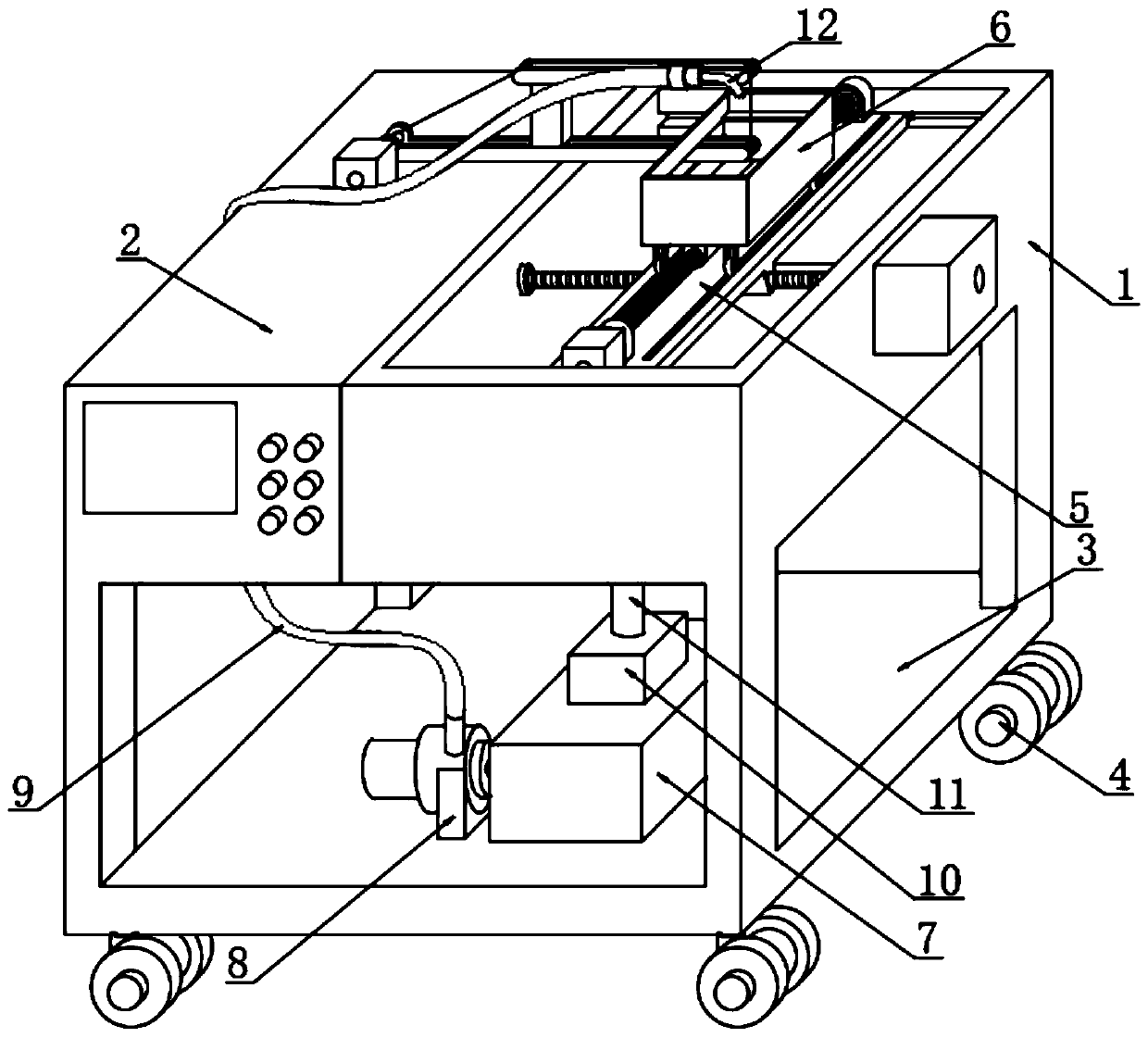
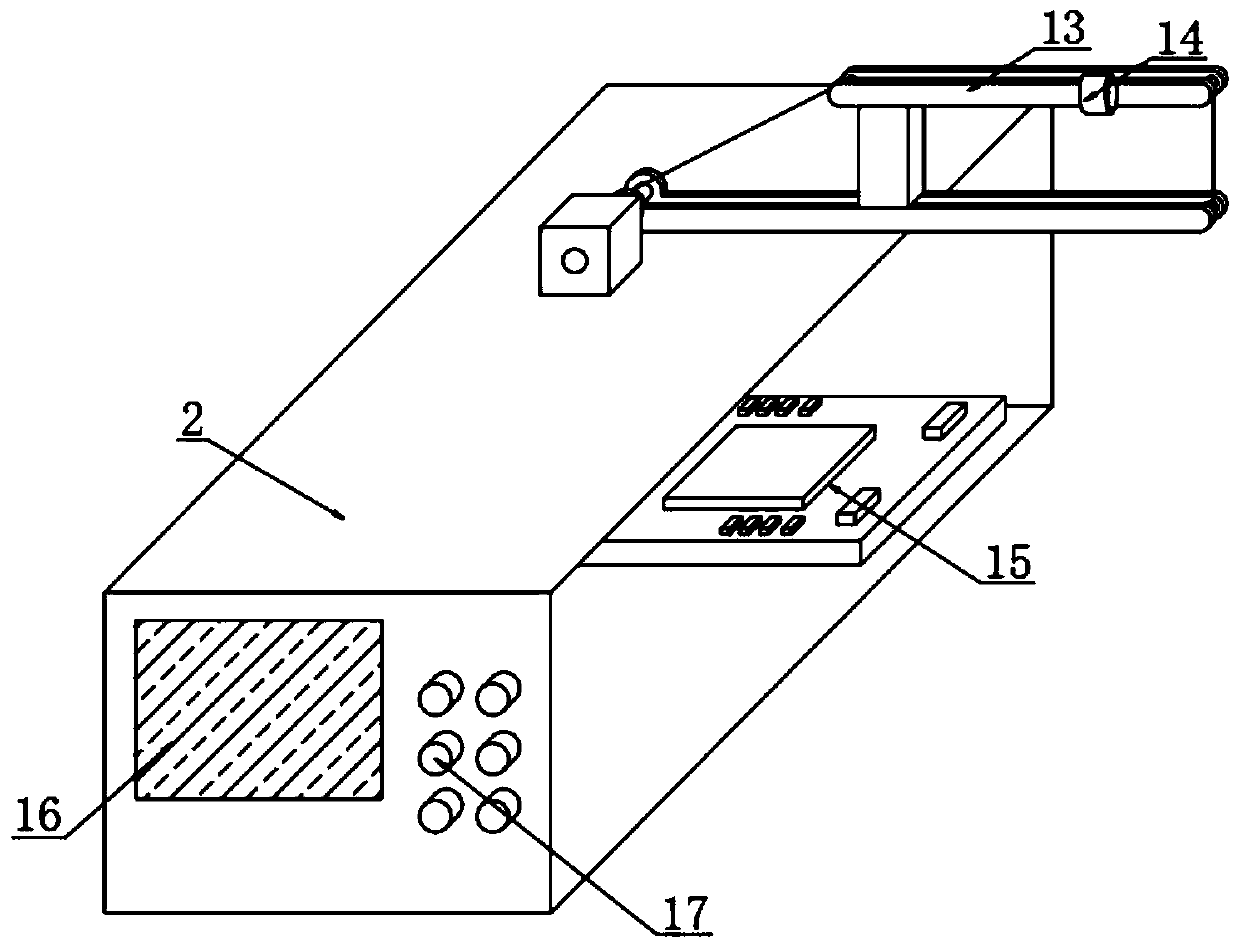
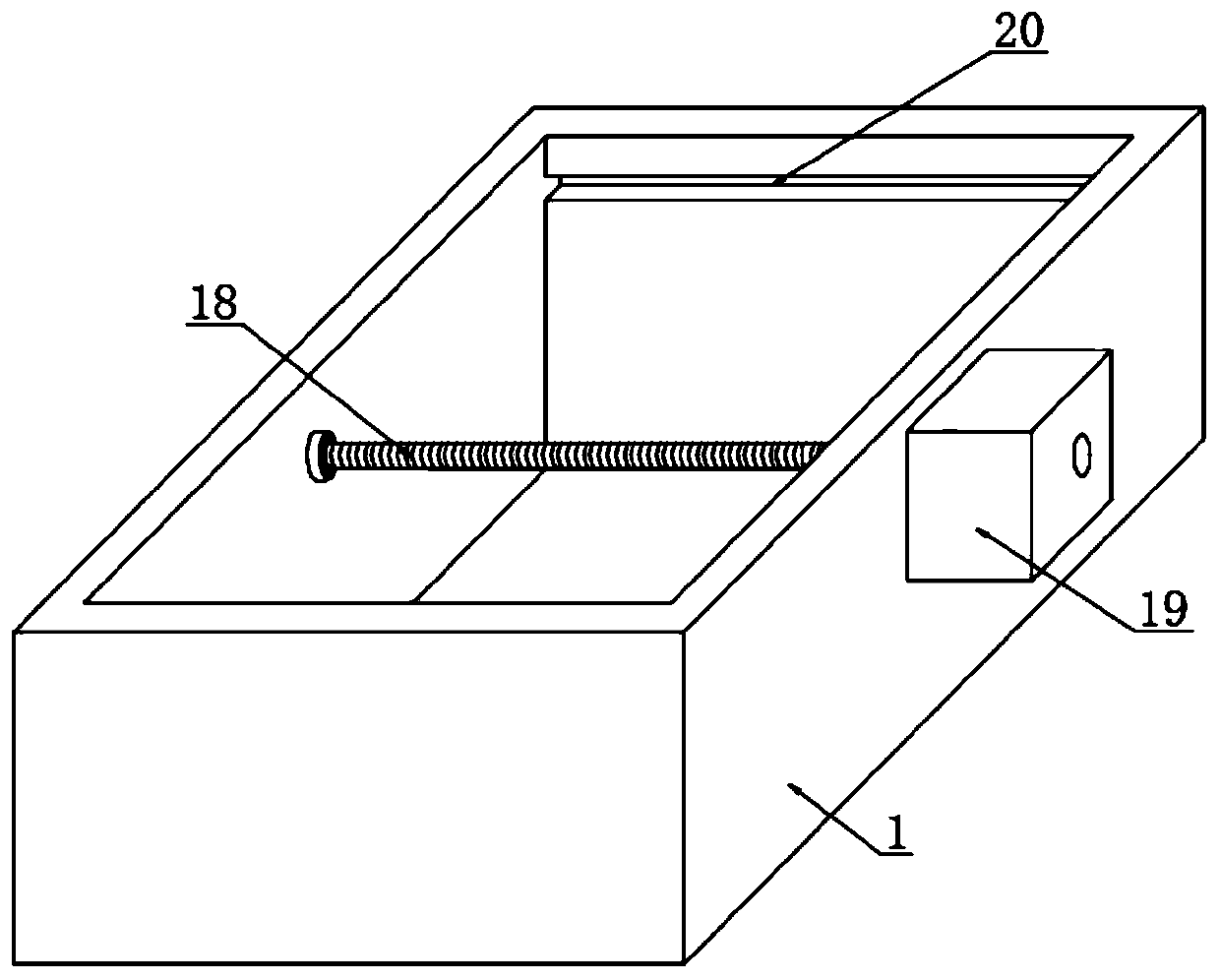
[0023] see Figure 1~5 , in an embodiment of the present invention, a wire cutting device based on mold processing includes a cutting box 1, a control box 2 is welded on one side of the cutting box 1, a bottom plate 3 is welded on the bottom of the cutting box 1, and the bottom plate 3 A universal wheel 4 is welded on one side of the lower surface of the bottom plate, and a water tank 7 is installed on one side of the upper surface of the bottom plate 3. The u...


PUM


Abstract

The invention discloses a wire cutting device based on mold processing, and particularly relates to the technical field of mold processing. The wire cutting device includes a cutting box body, a control box body is welded to one side of the cutting box body, and a bottom plate is welded to the lower part of the cutting box body. Universal wheels are welded to one side of the lower surface of the bottom plate, a water tank is installed on one side of the upper surface of the bottom plate, a filter box is welded to the upper end of the water tank in a penetrating mode, and a waste liquid pipe iswelded to the upper surface of the filter box in a penetrating mode; and a water pump is installed on one side of the water tank in a penetrating mode, a liquid conveying pipe is connected to the upper end of the water pump in a penetrating mode, a nozzle is installed at one end of the liquid conveying pipe in a penetrating mode, a displacement assembly is slidably connected into the cutting boxbody, and a water blocking plate is slidably connected to the upper surface of the displacement assembly. The wire cutting device based on the mold processing is provided with a coolant circulating device, is electrically adjusted, is small in size, and is provided with the universal wheels, and pulleys are arranged at the sliding connection positions.

Description

technical field [0001] The invention relates to the technical field of mold processing, in particular to a wire cutting device based on mold processing. Background technique [0002] Mold processing refers to the processing of forming and billet tools, and also includes shearing dies and die-cutting dies. Usually, the die is composed of an upper die and a lower die. The steel plate is placed between the upper and lower dies. The forming of the material is realized under the action of the press. When the press is opened, the workpiece determined by the shape of the mold will be obtained or the corresponding waste will be removed. The workpieces as small as electronic connectors and as large as automobile dashboards can be molded. The mold entry refers to a set of molds that can automatically move the workpiece from one station to another, and obtain the formed parts at the last station. The mold processing technology includes: cutting mold, punching mold, composite mold, Ext...

Claims


Application Information

Patent Timeline
Patent Type & Authority Applications(China)
IPC IPC(8): B23H7/02B23H7/26B23H11/00
CPCB23H7/02B23H7/26B23H11/00
Inventor 郦张炯
Owner 嘉兴德衡智能装备有限公司
Learn More