Crankshaft throw timing sprocket press-fitting device

A timing sprocket and press-fitting device technology, which is applied in the field of press-fitting devices, can solve problems such as low product qualification rate and difficult timing angle control, and achieve the effects of improving qualification rate, avoiding skew, and improving press-fitting accuracy

Pending Publication Date: 2020-03-06
TAIZHOU HONGXIN CRANKSHAFT
View PDF2 Cites 2 Cited by
  • Summary
  • Abstract
  • Description
  • Claims
  • Application Information

AI Technical Summary

Problems solved by technology

[0004] The purpose of the present invention is to address the above-mentioned problems in the prior art, and propose a press-fitting device for the timing sprocket on the crank of the crankshaft, which solves the problems that the timing angle is difficult to control and the product qualification rate is low

Method used


Image

  • Crankshaft throw timing sprocket press-fitting device
  • Crankshaft throw timing sprocket press-fitting device
  • Crankshaft throw timing sprocket press-fitting device

Examples


Embodiment Construction

[0037] The following are specific embodiments of the present invention and in conjunction with the accompanying drawings, the technical solutions of the present invention are further described, but the present invention is not limited to these embodiments.

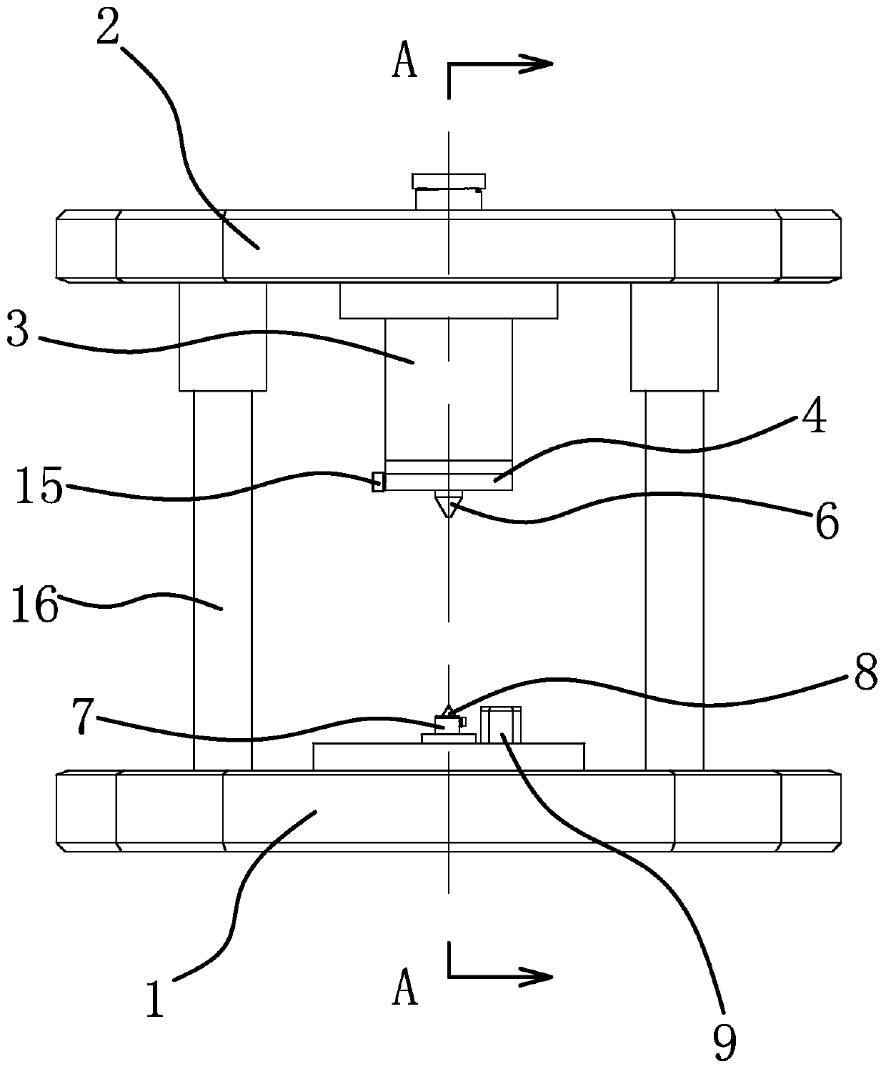
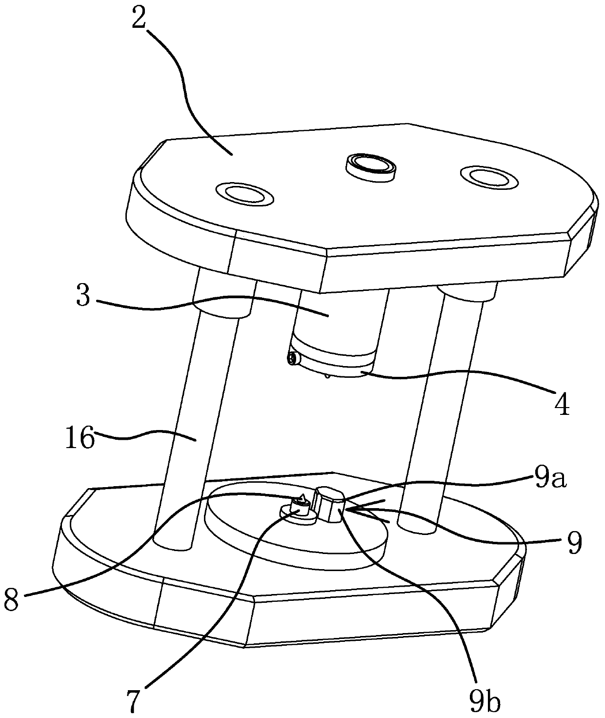
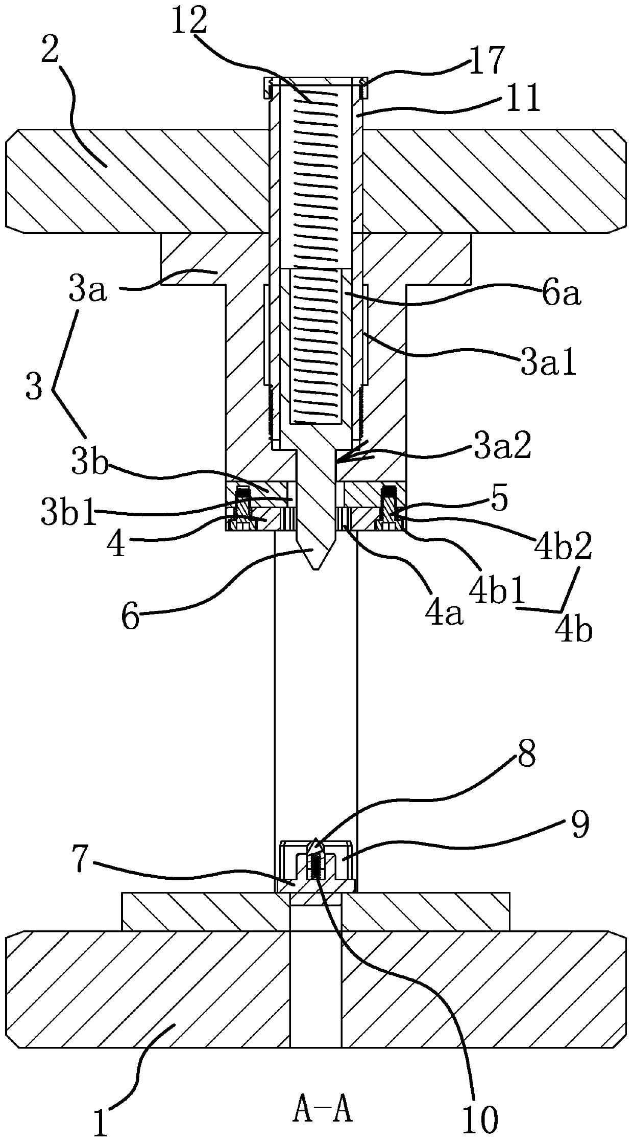
[0038] Such as Figure 1-Figure 3 As shown, the press-fitting device for the timing sprocket on the crank of the crankshaft includes a base 1 and a mold frame 2 that can be driven by a driving member to move to the base 1, wherein two parallel columns 16 are fixed on the base 1, and the mold The frame 2 is slidably arranged on the two columns 16, and the mold frame 2 is specifically driven by a cylinder or hydraulic pressure. A die head 3 is fixed on the mold frame 2, and the lower end surface of the die head 3 is fixed with a mounting block 4 by a fastener 5, and the center of the mounting block 4 is provided with a mounting groove 4 having the same shape as the timing sprocket 19. A floating top 6 is slidingly arranged ...


PUM


Abstract

The invention provides a crankshaft throw timing sprocket press-fitting device and belongs to the technical field of press-fitting equipment. Through the crankshaft throw timing sprocket press-fittingdevice, the problems that the timing angle is not easy to control and the product qualified rate is low during press-fitting are solved. The crankshaft throw timing sprocket press-fitting device comprises a base and a die carrier. A die head is fixed to the die carrier. A mounting block is fixed to the lower end face of the die head through fasteners. The center of the mounting block is providedwith a mounting groove in the same shape with a timing sprocket in a through mode. A floating center is slidably arranged in the die head in the vertical direction. The lower end of the floating center penetrates through the center of the mounting groove. A locating block is fixed to the base. A lower center is arranged in the center of the locating block. The axis of the lower center and the axisof the floating center are collinear. A pin capable of being inserted into a throw pin hole of a throw is arranged in the position, close to the locating block, of the base. A friction structure usedfor preventing the timing sprocket from going out is arranged in the mounting groove. The crankshaft throw timing sprocket press-fitting device has the advantages that the timing angle is easy to control, the press-fitting precision is high, the qualified rate is high, the structure is simple and the like.

Description

technical field [0001] The invention belongs to the technical field of press-fitting equipment, and relates to a press-fitting device for a timing sprocket on a crank of a crankshaft. Background technique [0002] The crankshaft is the key part that converts the linear motion of the cylinder piston into circular motion. It generally includes two symmetrically arranged cranks and a crank pin fixed between the two cranks. It is a connecting rod with a big end and a small end at both ends. When assembling, insert one end of the crank pin into the crank pin hole of a crank first, then put the big end of the connecting rod on the crank pin hole, and finally insert the other end of the crank pin into the crank pin hole of the other crank Crank pin hole, and then assembled into a crankshaft connecting rod assembly. When the crankshaft connecting rod is actually used, it is necessary to press-fit the timing sprocket on the corresponding crank of the crankshaft. The timing sprocket ...

Claims


Application Information

Patent Timeline
Patent Type & Authority Applications(China)
IPC IPC(8): B23P19/027
CPCB23P19/006B23P19/027
Inventor 李红兵
Owner TAIZHOU HONGXIN CRANKSHAFT
Why Eureka
Try Eureka