New energy resource charging pile with plug-in type charging gun and use method of new energy resource charging pile

A charging gun and new energy technology, which is applied in the field of new energy charging piles with plug-in charging guns, can solve the problem of poor rain resistance effect of charging piles, achieve good heat protection effect, good heat dissipation effect, and avoid accumulation. water effect

Inactive Publication Date: 2020-03-06
王双炎
View PDF7 Cites 4 Cited by
  • Summary
  • Abstract
  • Description
  • Claims
  • Application Information

AI Technical Summary

Problems solved by technology

[0004] The purpose of the present invention is to provide a new energy charging pile with a plug-in charging gun and its use method to solve the following technical problems: (1) Through the two-layer design of the outer pile body and the inner box, the entire charging The waterproof and heat-proof effect of the pile is better. At the same time, the inner box is connected to the inner wall of the outer pile through the connecting column, so that there is sufficient heat dissipation space between the inner box and the outer pile, so that the heat dissipation effect of the entire charging pile is better. Through the drive The output shaft of the motor drives the screw to rotate, and the screw cooperates with the nut to drive the water baffle down. The rod sleeve on the water baffle slides down along the vertical rod, and the water baffle slides down to the side of the cooling fins on the outer pile body. It can prevent rainwater from entering the outer pile body through the cooling fins when it rains. With this setting, because the outer pile itself is provided with cooling fins on both sides, it is easy for rainwater to enter the outer pile body from the cooling fins in outdoor rainy weather, making the outer pile There is accumulated water in the body, and a water shield that can be lifted up and down is installed. During normal use on sunny days, the water shield is raised to the top, so that the water shield will not cover the normal heat dissipation of the cooling fins, ensuring the normal heat dissipation of the entire charging pile. In rainy weather, the water retaining plate is lowered to the heat dissipation fins to prevent rainwater from entering the outer pile body through the heat dissipation fins, so as to solve the technical problem that the rain resistance effect of the charging pile in the prior art is not good; (2) by reducing the A number of clamping plates arranged at equal intervals are arranged on the shock shell, so that when the shock absorbing shell is impacted, the impact force can be distributed to each clamping plate position, effectively dispersing the impact force when the shock absorbing shell is impacted, and when the vehicle moves To the shock absorbing shell, the shock absorbing shell squeezes the corresponding fixed rod through the clamping plate, the first spring on the fixed rod contracts to make the fixed rod move on the supporting plate, and at the same time, the rotating rod between the clamping plate and the supporting plate rotates , the rotating rod rotates and squeezes the first spring column to shrink on the slot. Through this setting between the clamping plate and the support plate, when the clamping plate is impacted, it can pass through the first spring column and the first spring column on the fixing rod. A spring effectively reduces the impact on the support plate, and at the same time, it is set by the second spring column between the support plate and the rubber plate, so that the impact force on the rubber plate when the shock absorbing shell is hit is further reduced. The setting of the structure will greatly reduce the impact force and the damage caused when the front of the charging pile is hit by a car, and solve the technical problem that the front of the charging pile is easily damaged when the front of the charging pile is hit by a vehicle; (3) through Press the pressing plate, the front end of the pressing plate is upturned, and at the same time, the second spring stretches to push the rear end of the pressing plate, and then drives the pressing plate to move towards the charging plug, hold the handle, and connect the lock on the pressing plate to the car charging position card Through this setting, the charging gun on the charging pile can be plugged into the charging position of the car. During the charging process, no one needs to continue to hold the charging gun. The whole charging process is more convenient. When it rains, rainwater passes between the pressing plate and the installation slot. The gaps in the spring flow to the spring groove, and the absorbent cotton on the spring groove absorbs the rainwater, and the excess rainwater is blocked by the waterproof ring and the waterproof membrane, which solves the problem that the spring at the plug-in position of the charging gun on the charging pile is easily corroded by rainwater in the prior art question

Method used


Image

  • New energy resource charging pile with plug-in type charging gun and use method of new energy resource charging pile
  • New energy resource charging pile with plug-in type charging gun and use method of new energy resource charging pile
  • New energy resource charging pile with plug-in type charging gun and use method of new energy resource charging pile

Examples


Embodiment Construction

[0036] The technical solutions in the embodiments of the present invention will be clearly and completely described below in conjunction with the accompanying drawings in the embodiments of the present invention. Obviously, the described embodiments are only a part of the embodiments of the present invention, rather than all the embodiments. Based on the embodiments of the present invention, all other embodiments obtained by those of ordinary skill in the art without creative work shall fall within the protection scope of the present invention.

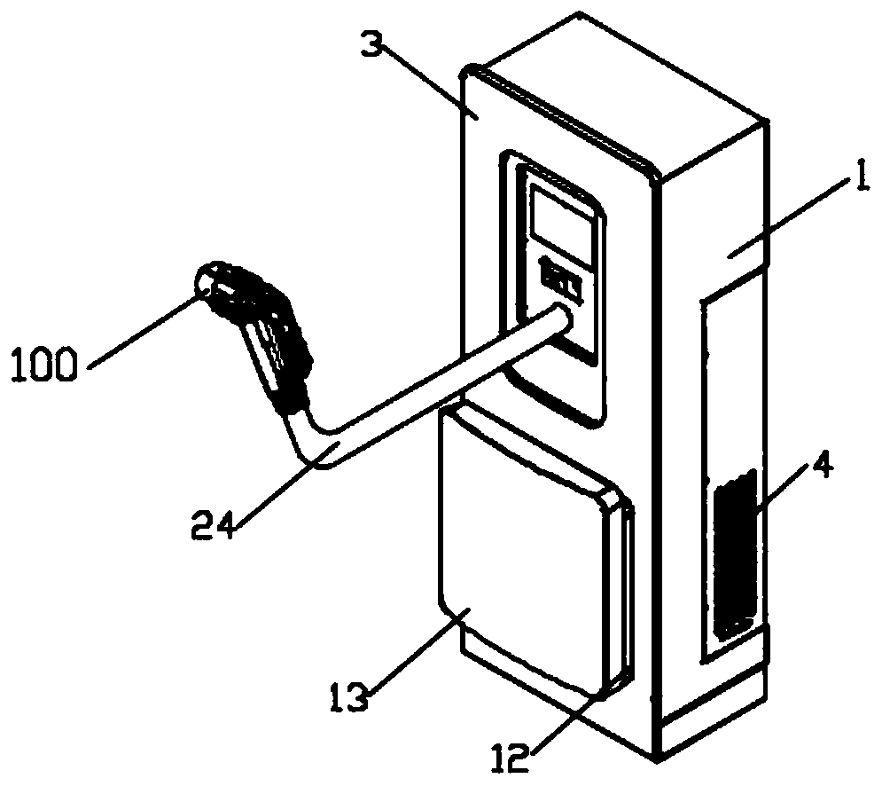
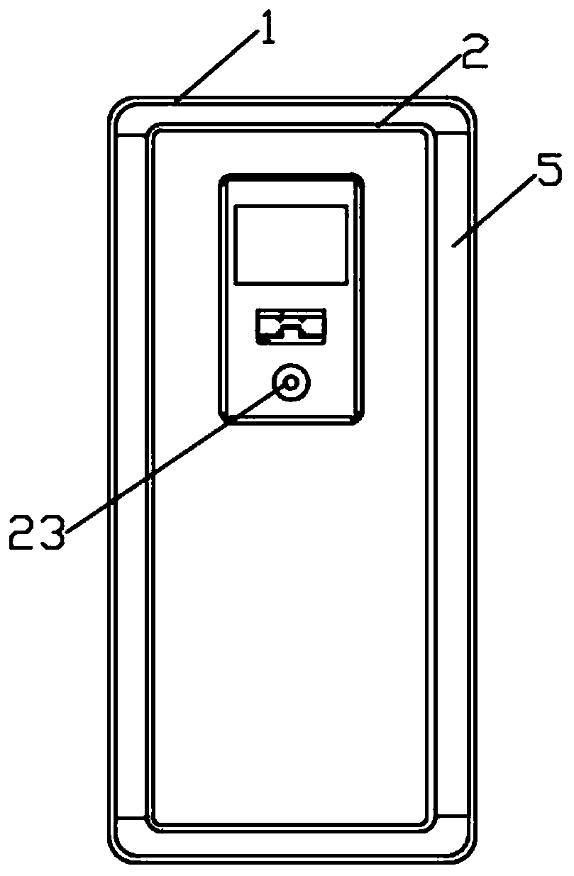
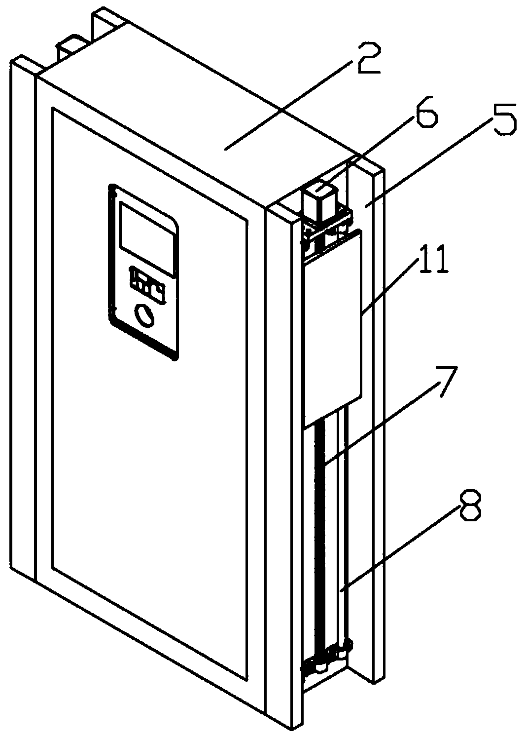
[0037] See Figure 1-10 As shown, the present invention is a new energy charging pile with a plug-in charging gun, which includes an outer pile body 1, a gun body 100, a pile door 3 is rotatably installed on one side of the outer pile body 1, and the outer pile body 1 The cavity is provided with an inner box body 2, four connecting posts 5 are installed symmetrically on both sides of the inner box body 2, a screw rod 7 is arranged betwee...


PUM


Abstract

The invention discloses a new energy resource charging pile with a plug-in type charging gun and a use method of the new energy resource charging pile. The new energy resource charging pile comprisesan outer pile body and a gun body. A pile door is installed on one side of the outer pile body in a rotating manner. An inner box body is arranged in an inner cavity of the outer pile body. Four connection columns are symmetrically installed on the outer walls of the two sides of the inner box body. A lead screw is arranged between every two adjacent connection columns. Nuts are arranged on the peripheral face of each lead screw in a rotating manner and are fixedly installed on a water baffle. By means of the inner and outer two-layer design of the outer pile body and the inner box body, the waterproof and heat-proof effects of the whole charging pile can be better; meanwhile, the inner box body is connected with the inner wall of the outer pile body through the connection columns, and therefore a sufficient cooling space can be formed between the inner box body and the outer pile body, and the cooling effect of the whole charging pile can be better; the lead screws are driven by output shafts of drive motors to rotate, the lead screws are used in cooperation with the nuts to drive the water baffles to fall, rod sleeves on the water baffles slide downwards along stand rods, the water baffles slide downwards to one sides of cooling fins on the outer pile body, and then rainwater can be prevented from entering the outer pile body through the cooling fins when it rains.

Description

Technical field [0001] The invention relates to the technical field of new energy charging piles, in particular to a new energy charging pile with a plug-in charging gun and a use method thereof. Background technique [0002] Car charging is an important link in the development of new energy vehicles. Insufficient charging system infrastructure will directly restrict the industrial development of new energy vehicles. With the advancement of technology, charging pile equipment capable of charging new energy vehicles has begun to appear in recent years. The input end is directly connected to the AC grid and the output end is equipped with a charging plug for charging new energy vehicles. [0003] The patent document (201810194042.1) discloses a new energy charging pile, which uses solar photovoltaic panels to collect solar radiation energy, converts it into electric energy and stores it in a battery, and then outputs it to a charging gun through an inverter to perform a Recharge. ...

Claims


Application Information

Patent Timeline
Patent Type & Authority Applications(China)
IPC IPC(8): B60L53/31B60L53/302B60L53/16
CPCB60L53/16B60L53/302B60L53/31Y02T10/70Y02T10/7072Y02T90/12Y02T90/14
Inventor 王双炎
Owner 王双炎
Why Eureka
Try Eureka