
Plasma generating device

A technology for generating device and plasma, applied in the field of ions, which can solve the problems of damage, plasma device damage, polarization loss, etc.

Inactive Publication Date: 2020-03-10
CHINA PETROLEUM & CHEM CORP +1
View PDF13 Cites 0 Cited by
  • Summary
  • Abstract
  • Description
  • Claims
  • Application Information

AI Technical Summary

Problems solved by technology

Under the complex electromagnetic field, the components of the plasma generating device will also produce conductance loss, polarization loss, induction loss, etc., resulting in deterioration or damage to the insulation of the device, and the plasma generating device may need to work continuously for a long time, and the working environment may be high temperature, High humidity, complex components, etc., the electrical insulation performance is the key to the safety and reliability of the plasma generator, therefore, it is very important to enhance the electrical insulation performance of the plasma generator
[0003] One of the main problems faced by the existing high-voltage discharge plasma generating device is insufficient insulation performance. During long-term operation or under harsh working environment, the plasma generating device is prone to partial discharge, which leads to deterioration or damage of the insulating material. Discharge or volume breakdown failure, resulting in damage to the plasma generating device
The existing technology often adopts methods such as increasing the size of insulating materials or replacing expensive high-performance insulating materials to reduce the probability of device damage, so it also has the disadvantage of poor economy

Method used


Image

  • Plasma generating device
  • Plasma generating device
  • Plasma generating device

Examples


Embodiment Construction

[0029] The specific implementation manners of the embodiments of the present invention will be described in detail below in conjunction with the accompanying drawings. It should be understood that the specific implementation manners described here are only used to illustrate and explain the embodiments of the present invention, and are not intended to limit the embodiments of the present invention.

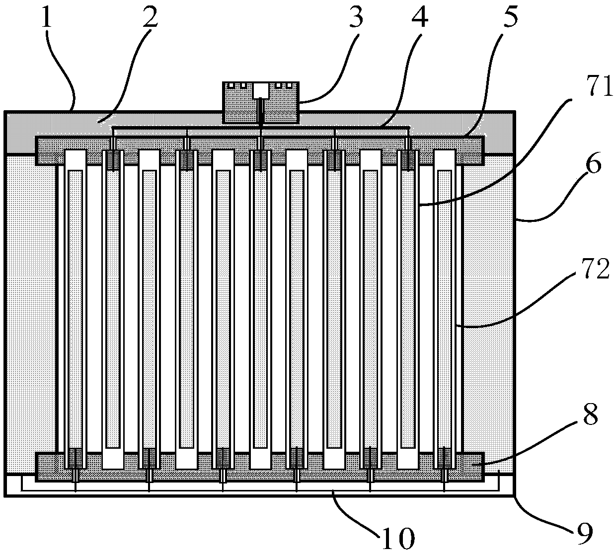
[0030] figure 1 is a sectional view of a plasma generator according to an embodiment of the present invention. Such as figure 1 As shown, the device includes: a high-voltage discharge tube 71 and a grounding discharge tube 72, the high-voltage discharge tube 71 and the grounding discharge tube 72 respectively have terminals; and a high-voltage side insulating support plate 5 and a grounding side insulating support plate 8, On the high-voltage-side insulating support plate 5 and the ground-side insulating support plate 8, through holes are respectively formed, and the terminals o...


PUM


Abstract

The invention relates to the technical field of plasmas, and specifically relates to a plasma generating device. The device comprises a high-voltage discharge tub, a grounding discharge tube, a high-voltage-side insulating support plate and a grounding-side insulating support plate, wherein the high-voltage discharge tube and the grounding discharge tube are respectively provided with wiring terminals; the high-voltage-side insulating support plate and the grounding-side insulating support plate are respectively provided with through wiring through holes, the wiring terminal of the high-voltage discharge tube is fixed on the high-voltage-side insulating support plate and is connected with a high-voltage power supply through the wiring through hole of the high-voltage-side insulating support plate, the grounding discharge tube is fixed on the grounding-side insulating support plate and is grounded through the wiring through hole of the grounding-side insulating support plate, and the high-voltage-side insulating support plate and the grounding-side insulating support plate are arranged on two opposite sides. According to the plasma generating device, the insulating property of the plasma generating device can be remarkably improved.

Description

technical field [0001] The invention relates to the field of plasma technology, in particular to a plasma generating device. Background technique [0002] Plasma is the fourth form of matter besides gas, liquid, and solid. It was first proposed by British physicist and chemist W. Crookes in 1879. The generation of plasma requires driving energy, which can be in the form of electricity, magnetism, light, heat, etc., and gas discharge under high voltage is the most commonly used plasma generation method, and the applied voltage waveform may be DC, AC, pulse or coupled and other forms. Under the complex electromagnetic field, the components of the plasma generating device will also produce conductance loss, polarization loss, induction loss, etc., resulting in deterioration or damage to the insulation of the device, and the plasma generating device may need to work continuously for a long time, and the working environment may be high temperature, High humidity, complex compon...

Claims


Application Information

Patent Timeline
Patent Type & Authority Applications(China)
IPC IPC(8): H05H1/24
CPCH05H1/24
Inventor 王世强刘全桢牟善军刘宝全唐诗雅牟洪祥关银霞
Owner CHINA PETROLEUM & CHEM CORP
Learn More