Angle steel cutting device capable of accurately positioning cutting length

A cutting length and accurate positioning technology, which is applied in the direction of shearing devices, shearing machine accessories, shearing machine equipment, etc., can solve the problems of inconvenient operation, easy deformation of angle steel, and irregular cutting end faces, etc., and achieve the effect of easy operation

Active Publication Date: 2020-03-13
浙江杭海镀锌钢管有限公司
View PDF8 Cites 0 Cited by
  • Summary
  • Abstract
  • Description
  • Claims
  • Application Information

AI Technical Summary

Problems solved by technology

[0005] Aiming at the deficiencies of the prior art, the present invention provides an angle steel cutting device capable of accurately positioning the cutting length, which is easy to operate, the angle steel after cutting is not easily deformed, the cutting end face is neat, the cutting length can be accurately positioned, and the angle steel after cutting is automatically stored It solves the problems of inconvenient operation of the general angle steel cutting device, easy deformation of the cut angle steel, irregular cutting end face, inability to accurately locate the cutting length, and the problem that the cut angle steel directly falls to the ground

Method used


Image

  • Angle steel cutting device capable of accurately positioning cutting length
  • Angle steel cutting device capable of accurately positioning cutting length
  • Angle steel cutting device capable of accurately positioning cutting length

Examples


Embodiment Construction

[0030] The technical solutions in the embodiments of the present invention will be clearly and completely described below with reference to the accompanying drawings in the embodiments of the present invention. Obviously, the described embodiments are only a part of the embodiments of the present invention, but not all of the embodiments. Based on the embodiments of the present invention, all other embodiments obtained by those of ordinary skill in the art without creative efforts shall fall within the protection scope of the present invention.

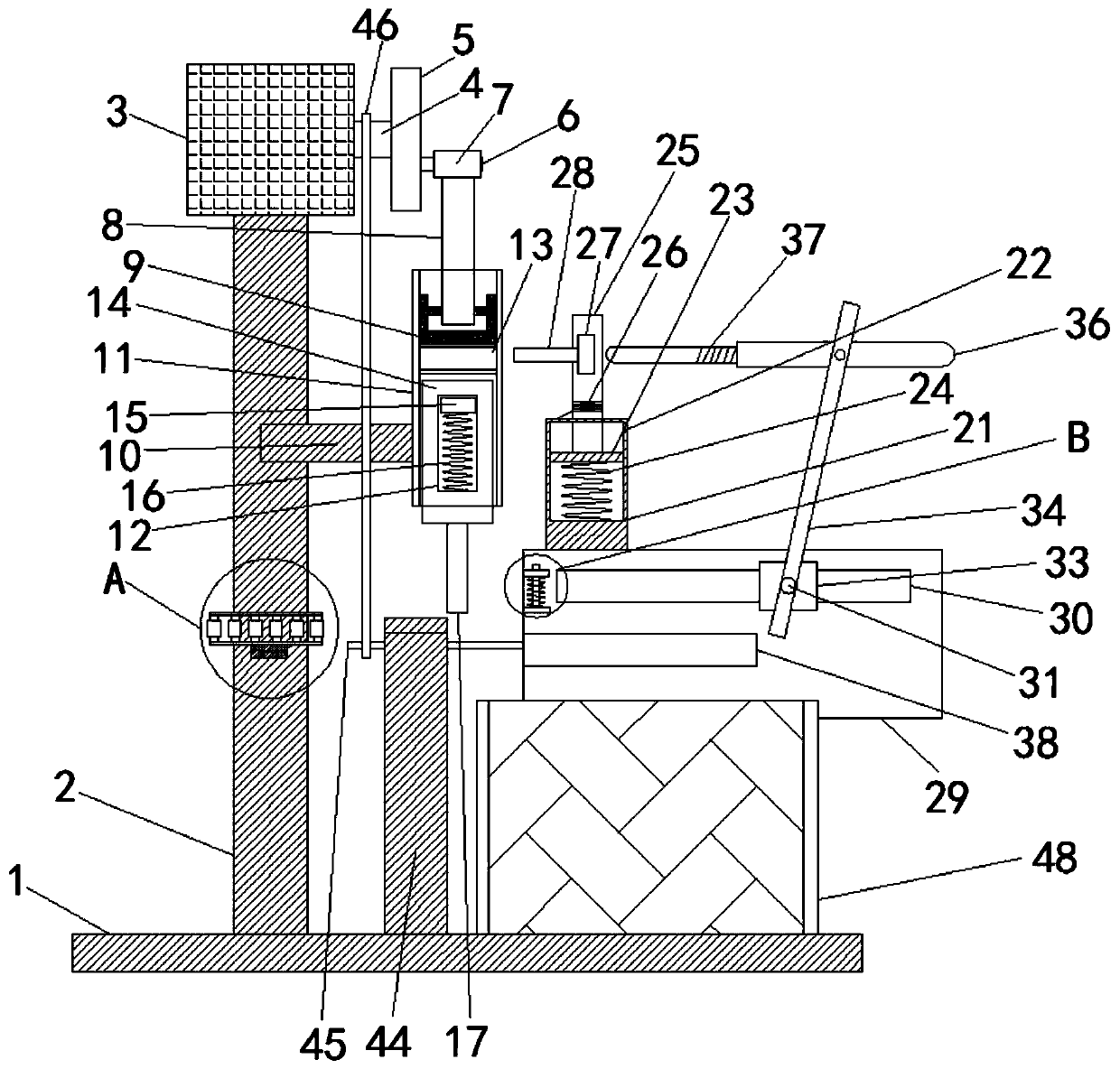
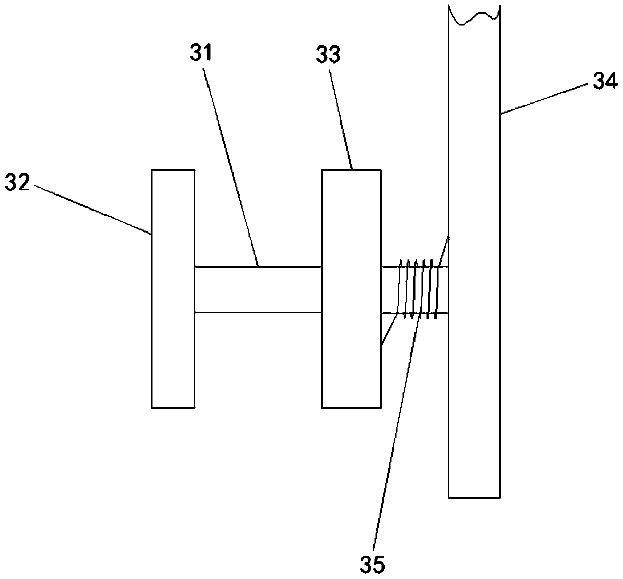
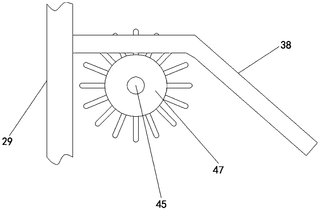
[0031] see Figure 1-8, an angle steel cutting device capable of accurately positioning the cutting length, comprising a base 1, a column 2 is fixedly installed above the base 1, a drive device 3 is fixedly installed on the upper front end of the column 2, and a drive shaft 4 is provided on the right side of the drive device 3 , the right side of the drive shaft 4 is fixedly connected with a turntable 5, the right side of the turntabl...


PUM


Abstract

The invention relates to the technical field of hardware fittings and discloses an angle steel cutting device capable of accurately positioning the cutting length. The device comprises a base. A column is fixedly installed on the base, a driving device is fixedly installed on the front end of the upper portion of the column, and a driving shaft is arranged on the right side of the driving device.A rotation disc is fixedly connected to the right side of the driving shaft, a horizontal rod is fixedly connected to the front end of the middle of the column, and a plunger cylinder is fixedly connected to the right end of the horizontal rod. A plunger is arranged in an inner cavity of the plunger cylinder, and an angle steel slotter is fixedly connected to the lower portion of the plunger. According to the angle steel cutting device capable of accurately positioning the cutting length, magnetic rollers are used for conveying angle steel, so that the angle steel extrudes a long rod to drivea press plate to be screwed into the plunger cylinder. In cooperation with a rotation piston, the press plate is extruded, so that the angle steel slotter falls down. The angle steel cutting device has the advantages that operation is easily and conveniently performed, the cut angle steel does not easily deform, the cutting end face is in order, the cutting length can be accurately positioned, andthe cut angle steel is automatically stored.

Description

technical field [0001] The invention relates to the technical field of hardware accessories, in particular to an angle steel cutting device capable of accurately positioning the cutting length. Background technique [0002] Hardware usually refers to the five metal materials of gold, silver, copper, iron and tin. Products made of hardware materials are usually divided into two categories: large hardware and small hardware. Angle steel belongs to large hardware, and angle steel is commonly known as angle steel. Iron is a long strip of steel whose two sides are perpendicular to each other. The angle steel can be composed of various stress-bearing components according to the different needs of the structure. The angle steel can also be used as a connector between the components. Angle steel is often seen. [0003] The angle steel is often in a long size when it leaves the factory. The user needs to use the machine to cut such long angle steel into smaller angle steel one by on...

Claims


Application Information

Patent Timeline
Patent Type & Authority Applications(China)
IPC IPC(8): B23D15/04B23D15/12B23D33/00B23D33/02B23D33/12
CPCB23D15/04B23D15/12B23D33/006B23D33/02B23D33/12
Inventor 刘源
Owner 浙江杭海镀锌钢管有限公司
Why Eureka
Try Eureka