Cart for gas shielded arc welding
A gas-shielded welding and cart technology, which is applied to trolleys, multi-axis trolleys, motor vehicles, etc., can solve the problem of inconvenient single-person gas shielded welding, and achieve the effect of improving convenience and avoiding the rollover of carts
- Summary
- Abstract
- Description
- Claims
- Application Information
AI Technical Summary
Problems solved by technology
Method used
Image
Examples
Embodiment 1
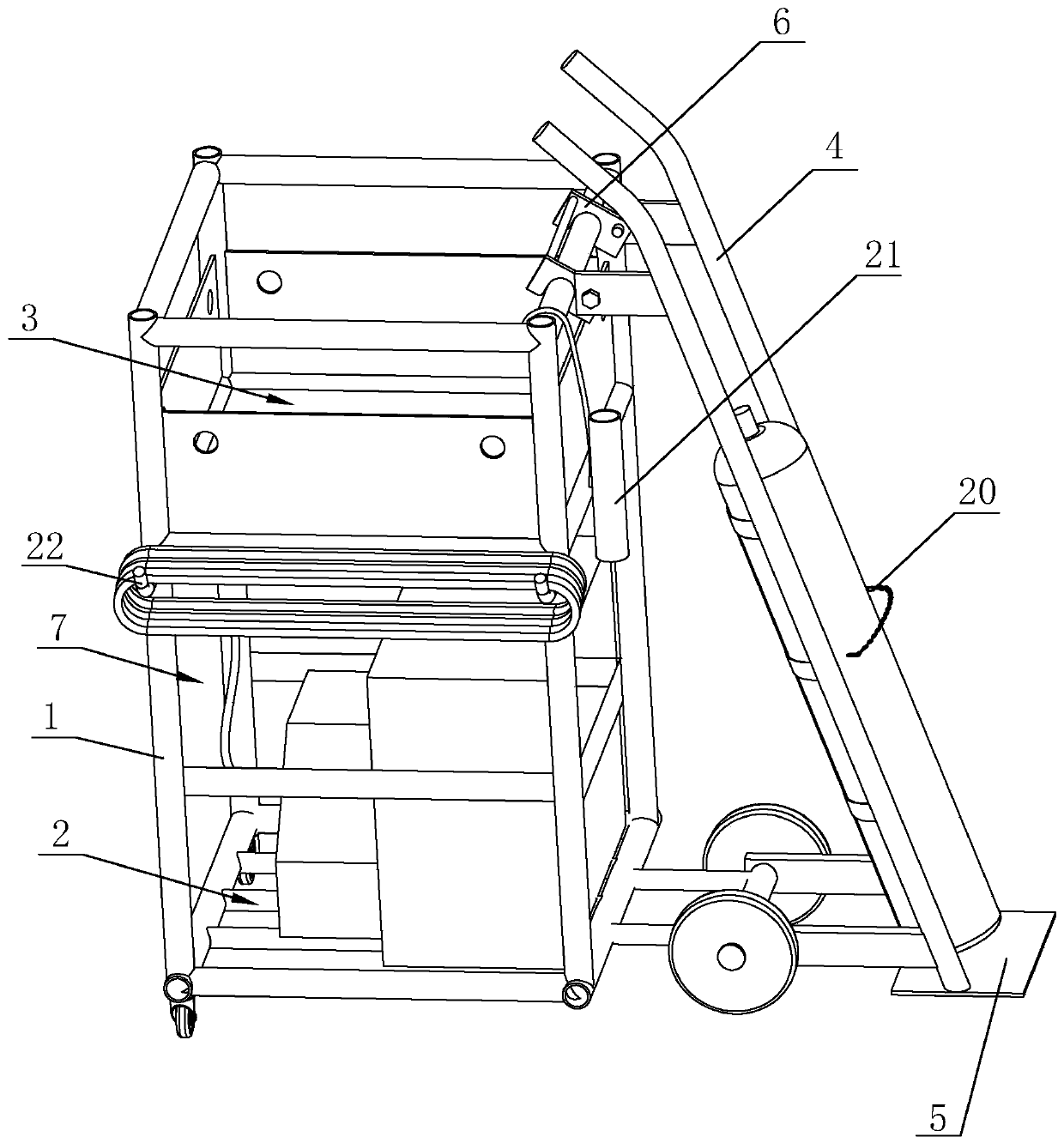
[0040] A trolley for gas shielded welding, such as figure 1 As shown, it includes a vehicle frame 1. A welding machine platform 2 is arranged on the vehicle frame 1. A storage tank 3 for placing auxiliary welding device supplies is provided on the vehicle frame 1 above the welding machine platform 2. A side of the vehicle frame 1 is rotated and provided with a Gas bottle frame 4, the lower end of gas bottle frame 4 is fixed with seesaw 5, and the upper end of gas bottle frame 4 is provided with the fixing piece that is used for tilting and fixing gas bottle frame 4, and the fixing piece is connected on the gas bottle frame 4 for rotation and is connected with The hook 6 that vehicle frame 1 cooperates. When in use, first place the welding machine on the welding machine platform 2, then push the vehicle frame 1 together with the gas cylinder frame 4 to the gas cylinder, use the seesaw 5 to rotate, so that the gas cylinder leans against the gas cylinder frame 4, and the gas cyli...
Embodiment 2
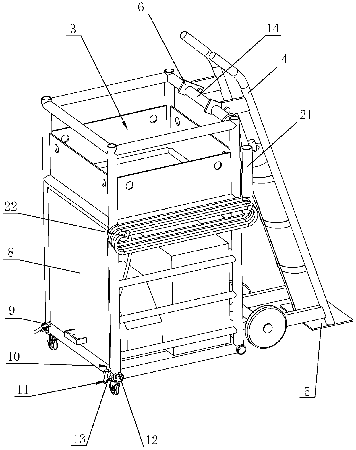
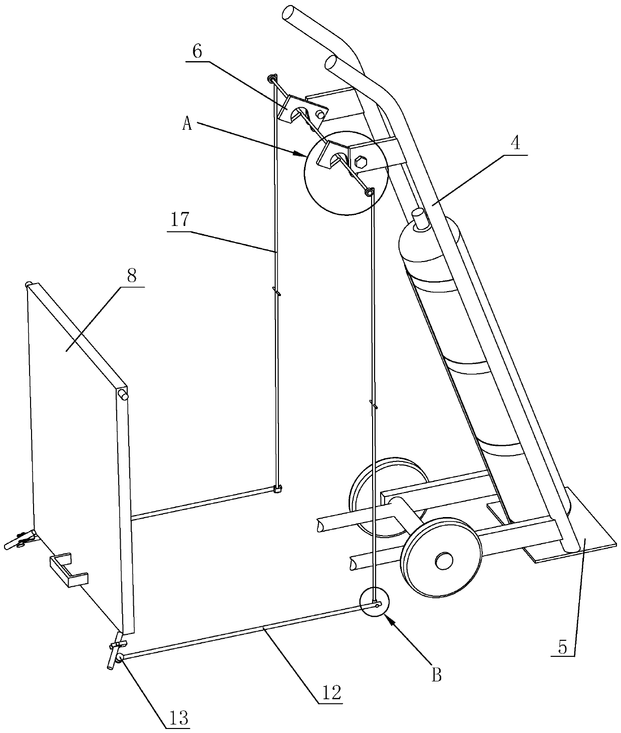
[0043] A trolley for gas shielded welding, such as figure 2 and image 3 As shown, the difference from Embodiment 1 is that the frame 1 is hingedly connected with a baffle 8 at the insertion opening 7, the hinge point of the baffle 8 is located on the upper side of the insertion opening 7, and the free end of the baffle 8 It is the lower side, that is, under the action of its own weight, the baffle plate 8 is in the state of closing the inlet 7, and the frame 1 is hingedly connected with a compression rod 9 at the free end of the baffle plate 8, and the hinge point of the compression rod 9 In the middle of its length direction, the two ends of the pressing rod 9 are the pressing end 10 and the triggering end 11 respectively. The telescoping rod 12 for pushing the triggering end 11 to rotate is arranged on the frame 1 . When in use, the telescopic rod 12 is stretched out to push the trigger end 11 to rotate, and then the abutment end 10 presses against the baffle 8 to compres...
PUM
 Abstract
Description
Claims
Application Information
 - R&D
- Intellectual Property
- Life Sciences
- Materials
- Tech Scout
- Unparalleled Data Quality
- Higher Quality Content
- 60% Fewer Hallucinations
Browse by: Latest US Patents, China's latest patents, Technical Efficacy Thesaurus, Application Domain, Technology Topic, Popular Technical Reports.
© 2025 PatSnap. All rights reserved.Legal|Privacy policy|Modern Slavery Act Transparency Statement|Sitemap|About US| Contact US: help@patsnap.com


