Valve timing control device
A control device and valve timing technology, applied in the direction of valve device, transmission device, engine control, etc., can solve expensive problems
- Summary
- Abstract
- Description
- Claims
- Application Information
AI Technical Summary
Problems solved by technology
Method used
Image

Examples
Embodiment Construction
[0036] In the following, reference will be made to Figure 1 to Figure 8 Embodiments according to the present disclosure are explained.
[0037] [Schematic Configuration of Valve Timing Control Device]
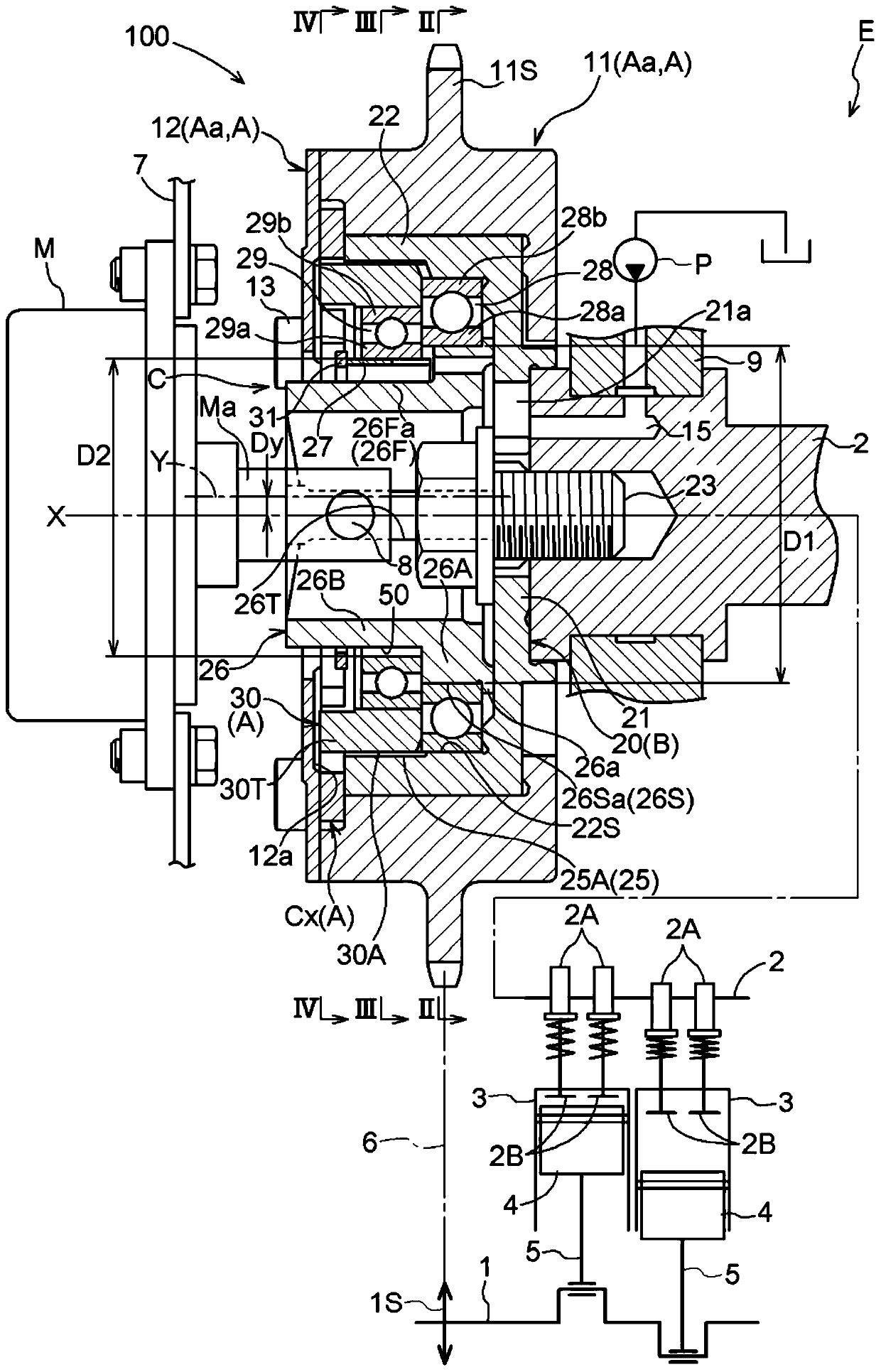
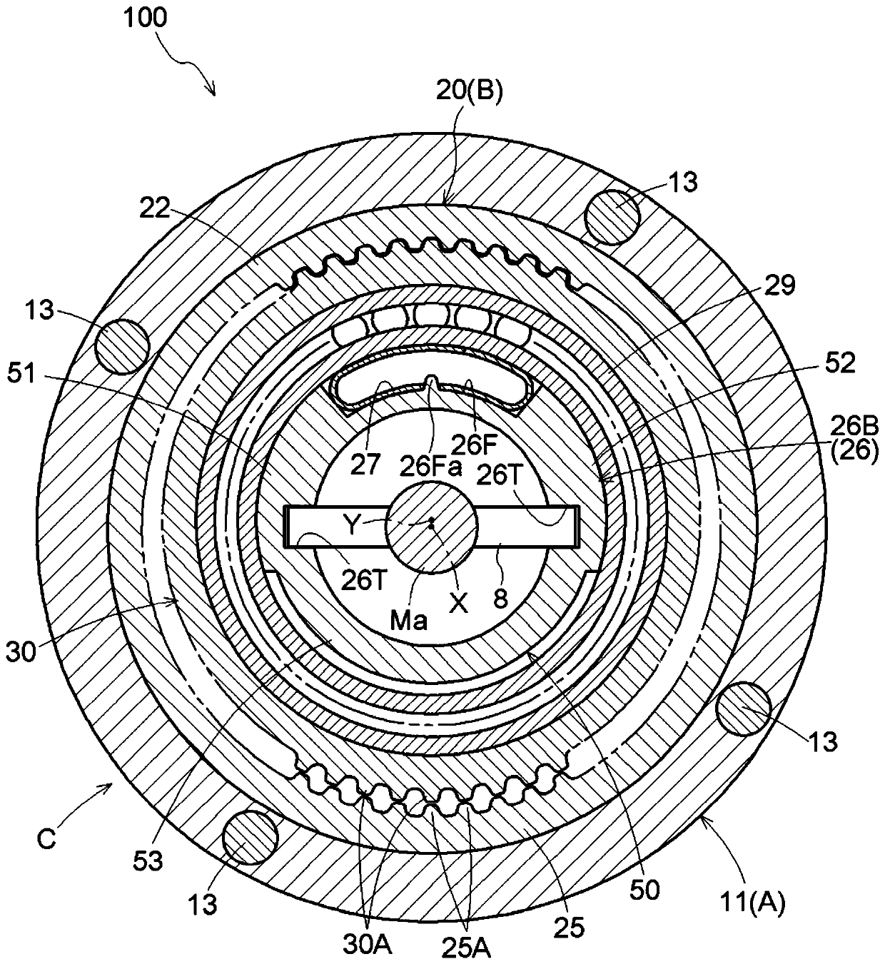
[0038] figure 1 A cross section of the valve timing control device 100 according to this embodiment is shown. Figure 5 An exploded perspective view of the valve timing control device 100 is shown.
[0039] Such as figure 1 As shown, the valve timing control device 100 includes a driving side rotary body A configured to rotate around a rotation axis X in synchronization with a crankshaft 1 of an engine E serving as an internal combustion engine; A member 20 (an example of a first gear) that is provided radially inside the drive side rotary body A and is configured to be integrated with a valve opening and closing intake camshaft 2 (an example of a camshaft) of the engine E centering on the rotary axis X and a phase adjustment mechanism C configured to set the relative rot...
PUM
 Abstract
Description
Claims
Application Information
 - R&D
- Intellectual Property
- Life Sciences
- Materials
- Tech Scout
- Unparalleled Data Quality
- Higher Quality Content
- 60% Fewer Hallucinations
Browse by: Latest US Patents, China's latest patents, Technical Efficacy Thesaurus, Application Domain, Technology Topic, Popular Technical Reports.
© 2025 PatSnap. All rights reserved.Legal|Privacy policy|Modern Slavery Act Transparency Statement|Sitemap|About US| Contact US: help@patsnap.com